Various ways of systematizing industrial manipulation robots can be found in the literature. Very often, the criteria used are based on their technical characteristics and are fully valid only for a certain period of time. A division based on the type of mechanical structure of the minimum robot configuration is adopted here, since it is one of the very important characteristics, and which is relatively unchanged over time. The basic configurations of industrial robots will be presented below.
Robot of anthropomorphic configuration:
In most robotic configurations, including this one, the first degree of freedom (calculated from the substrate) is rotational and the axis of the first joint is vertical. This joint ensures the rotation of the complete robot around the vertical axis. The axes of the second and third joints are mutually parallel, horizontal, and perpendicular to the axis of the first
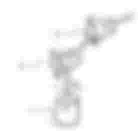
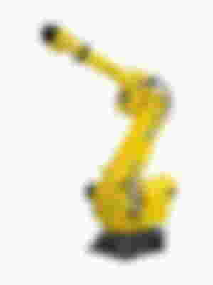
of the second and third joints, it is ensured that the top of the minimum configuration is positioned at an arbitrary point in the vertical plane containing the axis of the first joint. A sketch of the kinematic structure and a photograph of a robot of anthropomorphic configuration are shown in the figures. The mechanical structure of the robot of anthropomorphic configuration is adjusted to the structure of the human hand, so the name of the upper arm is often used for the second segment of the minimal configuration, and for the third forearm. The basic characteristic of a robot of anthropomorphic configuration is that it can cross an obstacle that gets in its way. If we look at the kinematic scheme of this configuration, it is clear that starting e.g. of the third joint affects the intensity of the moment around the axis of the second joint even if this joint does not move. This effect is called coupling. Therefore, it is said that if the movement of one joint significantly affects the driving moments (or driving forces if the joints are translational) of the other joints, the observed configuration has a significant coupling between the joints. Robots of anthropomorphic configuration are characterized by the fact that they have a large coupling between the joints
Robot of spherical (polar) configuration:
In the spherical configuration as well, the axis of the first joint is directed vertically upwards, while the axis of the second joint is horizontal and perpendicular to the axis of the first joint. The third joint is translational. Therefore, the spherical configuration of the species and the arrangement of the first two joints are the same as in the anthropomorphic one. Kinematic scheme of spherical conf
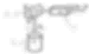
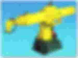
duration is shown in the figure. As before, the second and third joints allow the position of the top of the minimum configuration to be positioned at any point in the vertical plane, while rotating the vertical plane around the axis of the first joint, the robot tip can be positioned anywhere within the workspace. This configuration is called spherical because of the shape of the workspace that is part of the sphere, and polar because the angle of rotation of the second joint and the elongation of the third joint corresponds to the polar coordinates. It should be noted that, since the third joint is translational, the approach to the workplace should be unobstructed since a robot of this configuration cannot bypass them.
Cylindrical robot configuration:
The minimum configuration of a robot of cylindrical configuration has one rotary and two translational joints. In this, as in the previous configurations, the first segkinematska_sema_cilindricna.jpgment represents a rotating column around the vertical cylindric, so the first joint is rotary and placed in the same way as in the previous configurations. The second and third joints are translational (linear). The axis of the second joint is vertical, which means that its movement raises or lowers the complete structure that is further from the joint, towards the top of the robot. The axis of the third joint is horizontal so that by moving it, the gripper moves or moves away from the vertical column of the robot. This configuration is called cylindrical according to the shape of the workspace that is part of the cylinder. Robots of this configuration have very little coupling between the joints.


Robot care configuration:
SCARA configuration robots (Selective Compliance Assembly Robot Arm) have two rotary and one translator joint. Two mutually parallel rotary joints with vertical axes of rotation are placed on the column base so that both segments move in a horizontal plane.

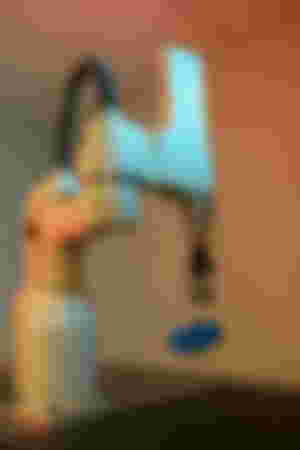
also vertical as seen in the figure. The grip joint usually has only one degree of freedom and that rotation around the vertical axis. Therefore, SCARA configuration robots typically have only four degrees of freedom. By moving the rotary joints, the positioning of the translator's joint is performed in the desired point of the horizontal plane, and then by lowering the translator's joint, the gripper is brought to the desired position within the working space. The SCARA configuration has very little coupling between the joints since the gravitational load is fully received by the mechanical structure of the rotary joints itself. Robots of the SCARA configuration were first realized in Japan in 1972, and are mainly intended for the realization of assembly tasks. They are characterized by high positioning accuracy and speed of work, as well as relatively high load capacity. The biggest disadvantage of the S
CARA robot comes from its construction - it is placed high and occupies a large part of the space above the space in which the work tasks are performed so that space must be free.
Robot of Cartesian (rectangular) configuration:
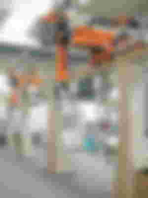
The minimal configuration of these robots, as can be seen from the figure, consists of three translational joints whose axes are parallel to the axes of Cartesian rectangular coordinate system kinematic_sema_decartous. Hence the name of this configuration you can find several other names: rectangular, Cartesian (Cartesian), or portal (gantry) configuration if the robot is placed on a stand that rises above the workspace to which it accesses from above). Considering the type and arrangement of joints in robots of this configuration, the contribution of movement in each of the joints to the movement of the gripper is clear, which makes programming and even manual guidance much easier. The working space is a parallelepiped whose dimensions depend on the range of motion of each joint. Robots of this configuration have very little coupling between the joints. In order to reduce the occupied space in the drive, robots of this configuration are very often placed on a stand that rises above the working machine (portal or gantry robot). Of course, in such cases, access to the working space of the working machine must be free from above. The dimensions of the stand can be such that the robot can service several machines.

Parallel robots:
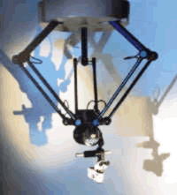
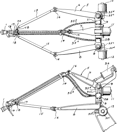
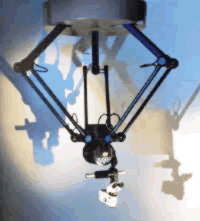
All the configurations described so far had the basic form of a kinematic chain, and only the type and disposition of the joints differed. In that sense, parallel robots are fundamentally different comparably instructively, but we believe that parallel needs to be mentioned here. They represent two platforms (in the nominal position these platforms are parallel) which are connected by segments of variable length. One platform is considered a base or base (upper platform), and the other is a working one whose position and orientation are controlled and there is a handle on it. By changing the distance between the corresponding joints on the base and work platform, the position and orientation of the work platform on which the gripper or tool that the robot carries is changed. The change in the distance between the joints on the base and working platform can be realized either by segments of variable length (telescopic segments with translational joints) or as two-segment elements with rotating joints as shown in the figure. Robots of this configuration are characterized by exceptional agility (speed of movement when moving from one position to another), high rigidity of position holding and relatively low mass in relation to the load capacity since each segment (arm) carries only one-third of the load, unlike kinematic chain type robots where each segment suffers the entire load.
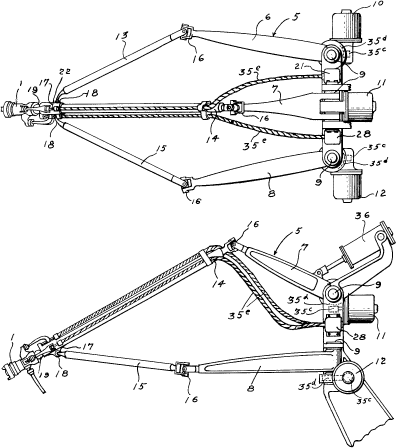







A wood splitter called a bonsek also works according to this system. Although the Fiat company is a new line it is pure robotics