In the previous episode, we got into texturing, texture filtering and also dithering. However, all that we rendered so far was a flat plane, which is not very impressive. Unless you want a 2D game based around nothing but sprites, you're going to need to render more complex 3D scenes.
A more advanced pipeline
Obviously, if you intend to render the "more complex 3D scenes", you're not going to be passing clip-space coordinates to the renderer directly. You're going to want to transform your models by using some hacky matrix maths. And for that, we need a more advanced "vertex shader" with a more advanced "uniform".
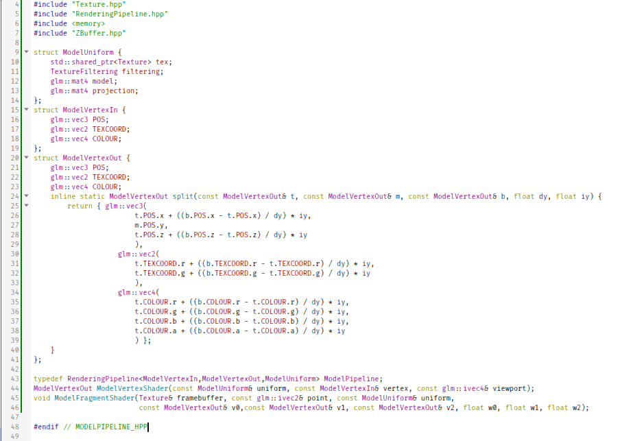
#ifndef MODELPIPELINE_HPP
#define MODELPIPELINE_HPP
#include <glm/glm.hpp>
#include "Texture.hpp"
#include "RenderingPipeline.hpp"
#include <memory>
#include "ZBuffer.hpp"

struct ModelUniform {
	std::shared_ptr<Texture> tex;
	TextureFiltering filtering;
	glm::mat4 model;
	glm::mat4 projection;
};
struct ModelVertexIn {
	glm::vec3 POS;
	glm::vec2 TEXCOORD;
	glm::vec4 COLOUR;
};
struct ModelVertexOut {
	glm::vec3 POS;
	glm::vec2 TEXCOORD;
	glm::vec4 COLOUR;
	inline static ModelVertexOut split(const ModelVertexOut& t, const ModelVertexOut& m, const ModelVertexOut& b, float dy, float iy) {
		return { glm::vec3(
			t.POS.x + ((b.POS.x - t.POS.x) / dy) * iy,
			m.POS.y,
			t.POS.z + ((b.POS.z - t.POS.z) / dy) * iy
			),
			glm::vec2(
			t.TEXCOORD.r + ((b.TEXCOORD.r - t.TEXCOORD.r) / dy) * iy,
			t.TEXCOORD.g + ((b.TEXCOORD.g - t.TEXCOORD.g) / dy) * iy
			),
			glm::vec4(
			t.COLOUR.r + ((b.COLOUR.r - t.COLOUR.r) / dy) * iy,
			t.COLOUR.g + ((b.COLOUR.g - t.COLOUR.g) / dy) * iy,
			t.COLOUR.b + ((b.COLOUR.b - t.COLOUR.b) / dy) * iy,
			t.COLOUR.a + ((b.COLOUR.a - t.COLOUR.a) / dy) * iy
			) };
	}
};

typedef RenderingPipeline<ModelVertexIn,ModelVertexOut,ModelUniform> ModelPipeline;
ModelVertexOut ModelVertexShader(const ModelUniform& uniform, const ModelVertexIn& vertex, const glm::ivec4& viewport);
void ModelFragmentShader(Texture& framebuffer, const glm::ivec2& point, const ModelUniform& uniform,
						 const ModelVertexOut& v0,const ModelVertexOut& v1, const ModelVertexOut& v2, float w0, float w1, float w2);

#endif // MODELPIPELINE_HPP

#include "ModelPipeline.hpp"
#include <glm/gtc/matrix_transform.hpp>

ModelVertexOut ModelVertexShader(const ModelUniform &uniform, const ModelVertexIn &vertex, const glm::ivec4 &viewport)
{

	ModelVertexOut out{ glm::projectNO(vertex.POS,uniform.model,uniform.projection,viewport), vertex.TEXCOORD, vertex.COLOUR };
	return out;
}

void ModelFragmentShader(Texture &framebuffer, const glm::ivec2 &point, const ModelUniform &uniform, const ModelVertexOut &v0, const ModelVertexOut &v1, const ModelVertexOut &v2, float w0, float w1, float w2)
{
	if(!uniform.tex) return;
	if(point.x < 0 || point.y < 0) return;
	glm::vec2 texCoord = {
			(w0 * v0.TEXCOORD.r) + (w1 * v1.TEXCOORD.r) + (w2 * v2.TEXCOORD.r),
			(w0 * v0.TEXCOORD.g) + (w1 * v1.TEXCOORD.g) + (w2 * v2.TEXCOORD.g)
					};
	glm::vec4 colourKernel = uniform.tex->sample(texCoord,point,uniform.filtering) * glm::vec4{
			(w0 * v0.COLOUR.r) + (w1 * v1.COLOUR.r) + (w2 * v2.COLOUR.r),
			(w0 * v0.COLOUR.g) + (w1 * v1.COLOUR.g) + (w2 * v2.COLOUR.g),
			(w0 * v0.COLOUR.b) + (w1 * v1.COLOUR.b) + (w2 * v2.COLOUR.b),
			(w0 * v0.COLOUR.a) + (w1 * v1.COLOUR.a) + (w2 * v2.COLOUR.a)
					};
	framebuffer.setPixelDithered(point,point,colourKernel);
}
Now, the things to unpack here:
This pipeline mixes the sampled texture colour with the per-vertex colour.
What are those two new uniform variables? Model and Projection?
Both are 4x4 matrices. We multiply our original object-space coordinates with them. I could write paragraphs upon paragraphs on the matrix mathematics involved, but what you need to know is that these matrix multiplications will take your object-space coordinates, transform them first into world-space coordinates (via multiplication with Model), then from world-space coordinates into clip-space coordinates and finally screen-space coordinates (via multiplication with Projection).
In your typically hardware-accelerated application, you actually have three such matrices: Model, View and Projection. By multiplying our object-space coordinates with the Model matrix, we get our world-space coordinates. By multiplying our world-space coordinates with View, we get our clipspace coordinates. By multiplying our clipspace coordinates with Projection, we get our screenspace coordinates. In this program, our "projection" is actually Projection multiplied by View, so we translate world-space coordinates into screen-space coordinates in one stage rather than two.
We obviously need to set these new variables somehow.... but how?
As I mentioned, our "projection" really is the merger of two other variables - a projection frustum matrix and a view matrix. The frustum matrix is rather trivial: just pick either glm::frustum, glm::perspective or glm::perspectiveFov. To keep things simple, I went with glm::frustum.
glm::frustum(-1.0f, 1.0f, -1.0f, 1.0f, 1.0f, 100.0f);But we need to also have a view matrix. How will we get it?
Enter the camera
The view matrix is supposed to represent the location of our camera or eyes, and the direction it is looking at.
For this purpose, I brought back an old camera class of mine, which I probably cobbled together from the code of programmers more skilled than me, which kind of makes it black magic to me.
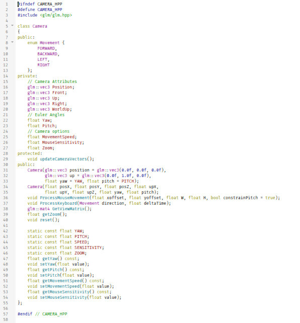
#ifndef CAMERA_HPP
#define CAMERA_HPP
#include <glm/glm.hpp>

class Camera
{
public:
	enum Movement {
		FORWARD,
		BACKWARD,
		LEFT,
		RIGHT
	};
private:
	// Camera Attributes
	glm::vec3 Position;
	glm::vec3 Front;
	glm::vec3 Up;
	glm::vec3 Right;
	glm::vec3 WorldUp;
	// Euler Angles
	float Yaw;
	float Pitch;
	// Camera options
	float MovementSpeed;
	float MouseSensitivity;
	float Zoom;
protected:
	void updateCameraVectors();
public:
	Camera(glm::vec3 position = glm::vec3(0.0f, 0.0f, 0.0f),
		   glm::vec3 up = glm::vec3(0.0f, 1.0f, 0.0f),
		   float yaw = YAW, float pitch = PITCH);
	Camera(float posX, float posY, float posZ, float upX,
		   float upY, float upZ, float yaw, float pitch);
	void ProcessMouseMovement(float xoffset, float yoffset, float W, float H, bool constrainPitch = true);
	void ProcessKeyboard(Movement direction, float deltaTime);
	glm::mat4 GetViewMatrix();
	float getZoom();
	void reset();

	static const float YAW;
	static const float PITCH;
	static const float SPEED;
	static const float SENSITIVITY;
	static const float ZOOM;
	float getYaw() const;
	void setYaw(float value);
	float getPitch() const;
	void setPitch(float value);
	float getMovementSpeed() const;
	void setMovementSpeed(float value);
	float getMouseSensitivity() const;
	void setMouseSensitivity(float value);
};

#endif // CAMERA_HPP
And the Camera.cpp, which is too big for a screenshot:
#include "Camera.hpp"
#include <glm/gtc/matrix_transform.hpp>

const float Camera::YAW = 3.14f;
const float Camera::PITCH = 0.0f;
const float Camera::SPEED = 2.5f;
const float Camera::SENSITIVITY = 0.005f;
const float Camera::ZOOM = 45.0f;

Camera::Camera(glm::vec3 position, glm::vec3 up, float yaw, float pitch)
	: MovementSpeed(SPEED),
	  MouseSensitivity(SENSITIVITY), Zoom(ZOOM)
{
	Front = glm::vec3(0.0f, 0.0f, 1.0f);
	Position = position;
	WorldUp = up;
	Yaw = yaw;
	Pitch = pitch;
	updateCameraVectors();
}
float Camera::getZoom()
{
	return Zoom;
}

void Camera::reset()
{
	Front = glm::vec3(0.0f, 0.0f, 1.0f);
	Position = glm::vec3(0.0f, 0.0f, 0.0f);
	WorldUp = glm::vec3(0.0f, 1.0f, 0.0f);
	Yaw = YAW;
	Pitch = PITCH;
	updateCameraVectors();
}
Camera::Camera(float posX, float posY, float posZ, float upX,
	   float upY, float upZ, float yaw, float pitch)
	: MovementSpeed(SPEED),
	  MouseSensitivity(SENSITIVITY), Zoom(ZOOM)
{
	Front = glm::vec3(0.0f, 0.0f, -1.0f);
	Position = glm::vec3(posX, posY, posZ);
	WorldUp = glm::vec3(upX, upY, upZ);
	Yaw = yaw;
	Pitch = pitch;
	updateCameraVectors();
}
void Camera::ProcessMouseMovement(float xoffset, float yoffset, float W, float H, bool constrainPitch)
{
	xoffset *= MouseSensitivity;
	yoffset *= MouseSensitivity;

	Yaw   += xoffset;
	Pitch += yoffset;

	// Make sure that when pitch is out of bounds, screen doesn't get flipped
	if (constrainPitch)
	{
		if (Pitch >= 3.14)
			Pitch = 3.14;
		if (Pitch <= -3.14)
			Pitch = -3.14;
	}

	// Update Front, Right and Up Vectors using the updated Euler angles
	updateCameraVectors();
}
void Camera::ProcessKeyboard(Movement direction, float deltaTime)
{
	float velocity = MovementSpeed * deltaTime;
	if (direction == FORWARD)
		Position += Front * velocity;
	if (direction == BACKWARD)
		Position -= Front * velocity;
	if (direction == LEFT)
		Position -= Right * velocity;
	if (direction == RIGHT)
		Position += Right * velocity;
}
glm::mat4 Camera::GetViewMatrix()
{
	return glm::lookAt(Position, Position + Front, Up);
}
float Camera::getYaw() const
{
	return Yaw;
}

void Camera::setYaw(float value)
{
	Yaw = value;
}

float Camera::getPitch() const
{
	return Pitch;
}

void Camera::setPitch(float value)
{
	Pitch = value;
}

float Camera::getMovementSpeed() const
{
	return MovementSpeed;
}

void Camera::setMovementSpeed(float value)
{
	MovementSpeed = value;
}

float Camera::getMouseSensitivity() const
{
	return MouseSensitivity;
}

void Camera::setMouseSensitivity(float value)
{
	MouseSensitivity = value;
}

void Camera::updateCameraVectors()
{
	Front = glm::vec3(
		cos(Pitch) * sin(Yaw),
		sin(Pitch),
		cos(Pitch) * cos(Yaw)
	);
	Front = glm::normalize(Front);
	Right = glm::vec3(
				sin(Yaw - 3.14f/2.0f),
				0.0f,
				cos(Yaw - 3.14f/2.0f)
			);
	Right = glm::normalize(Right);
	Up = glm::cross( Right, Front );
	Up = glm::normalize(Up);
}
So, just what in the name of RNGesus are we dealing with here?

In the source file, the first few lines after the header inclusions are a bunch of default constants, and they're not particularly interesting. What's far more interesting is the class's variables.
Position, as its name implies is the position of our camera in world-space.
Front is a 3D vector calculated from our Pitch and Yaw, and then normalized. Its pre-normalization values are
{ cos(pitch) * sin(yaw), sin(pitch), cos(pitch) * cos(yaw) }. How? Why? I don't know. It's black magic. Also, Pitch and Yaw are in radians, obviously.Right is calculated from Yaw, and then normalized. Its pre-normalization values are
{ sin(yaw - (3π/2)), 0, cos(yaw - (3π/2)) }. Another piece of our mysterious mathematical black magic.Up is calculated from Front and Right - as a matter of fact, it is the vector cross-product of Front and Right, but normalized afterwards.
But what the hell are Pitch and Yaw supposed to be anyway?
Euler angles, or more specifically, Tait-Byran angles. Basically, they represent the orientation of our camera.
So, with these variables at hand, what we do is this:
We manipulate the Yaw and Pitch based on mouse movement.
We manipulate Position based on keyboard movement.
To calculate our View matrix, we simply need use glm::lookAt.
glm::lookAt(Position, Position + Front, Up);Nice, now we have a camera that we can use to generate our View as well!
More complex shapes
Rendering just flat planes - especially ones consisting of two triangles or a single triangle - is boring. We need to import models into our renderer.
For this purpose, I recommend Assimp.
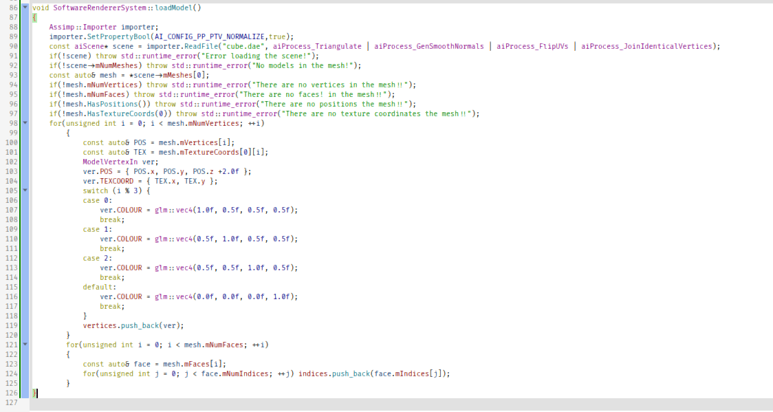
void SoftwareRendererSystem::loadModel()
{
	Assimp::Importer importer;
	importer.SetPropertyBool(AI_CONFIG_PP_PTV_NORMALIZE,true);
	const aiScene* scene = importer.ReadFile("cube.dae", aiProcess_Triangulate | aiProcess_GenSmoothNormals | aiProcess_FlipUVs | aiProcess_JoinIdenticalVertices);
	if(!scene) throw std::runtime_error("Error loading the scene!");
	if(!scene->mNumMeshes) throw std::runtime_error("No models in the mesh!");
	const auto& mesh = *scene->mMeshes[0];
	if(!mesh.mNumVertices) throw std::runtime_error("There are no vertices in the mesh!!");
	if(!mesh.mNumFaces) throw std::runtime_error("There are no faces! in the mesh!!");
	if(!mesh.HasPositions()) throw std::runtime_error("There are no positions the mesh!!");
	if(!mesh.HasTextureCoords(0)) throw std::runtime_error("There are no texture coordinates the mesh!!");
	for(unsigned int i = 0; i < mesh.mNumVertices; ++i)
		{
			const auto& POS = mesh.mVertices[i];
			const auto& TEX = mesh.mTextureCoords[0][i];
			ModelVertexIn ver;
			ver.POS = { POS.x, POS.y, POS.z +2.0f };
			ver.TEXCOORD = { TEX.x, TEX.y };
			switch (i % 3) {
			case 0:
				ver.COLOUR = glm::vec4(1.0f, 0.5f, 0.5f, 0.5f);
				break;
			case 1:
				ver.COLOUR = glm::vec4(0.5f, 1.0f, 0.5f, 0.5f);
				break;
			case 2:
				ver.COLOUR = glm::vec4(0.5f, 0.5f, 1.0f, 0.5f);
				break;
			default:
				ver.COLOUR = glm::vec4(0.0f, 0.0f, 0.0f, 1.0f);
				break;
			}
			vertices.push_back(ver);
		}
		for(unsigned int i = 0; i < mesh.mNumFaces; ++i)
		{
			const auto& face = mesh.mFaces[i];
			for(unsigned int j = 0; j < face.mNumIndices; ++j) indices.push_back(face.mIndices[j]);
		}
}
Now that we have our model, we can just set our model matrix to an identity matrix, maybe scale it up if we want....
pipeline.uniform.model = glm::mat4(1.0f);
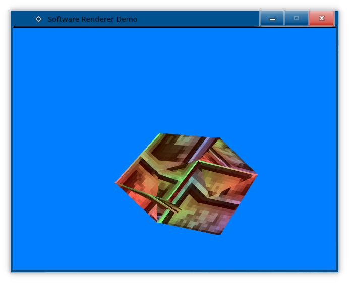
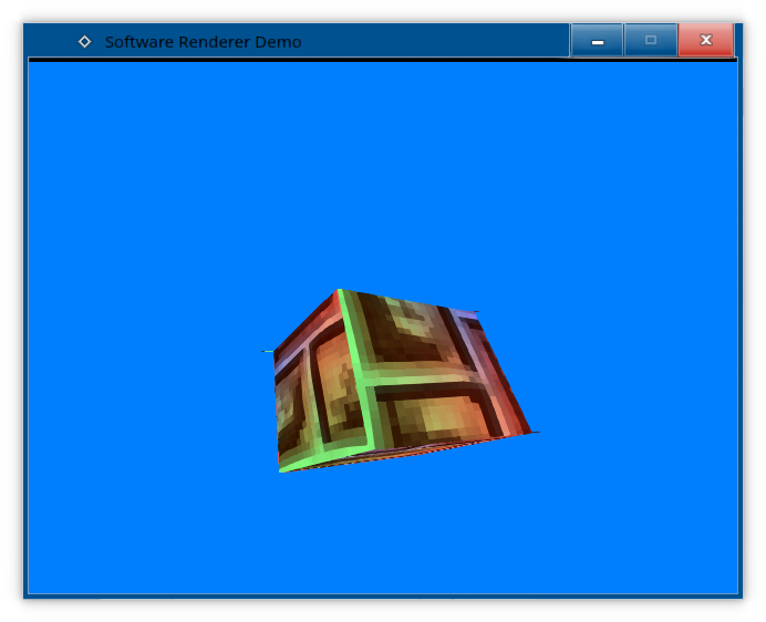
pipeline.uniform.model = glm::translate(pipeline.uniform.model, glm::vec3(0.0f, -1.75f, 0.0f)); // translate it down so it's at the center of the sceneAnd now we'll have our 3D scene with the cube.
Uh-oh. We did something terribly wrong, didn't we?
Those who are already familiar with 3D rendering pipelines should already know what's the problem here, but for those who don't...
The first problem at hand, is that we're not clearing our texture every time we render, so we end up constantly painting over what we have already painted, instead of starting with a blank canvas every frame. We solve this by adding a new function to textures: clearToColour().

virtual void clearToColour(const glm::vec4& colourKernel) = 0;And implement it on our StandardTexture:
	void clearToColour(const glm::vec4& colourKernel) {
		for(int x = 0; x < w; ++x) {
			for(int y = 0; y < h; ++y) {
				PixelType& pix = buff[((y) * w) + x];
				pix.fromKernelDithered(colourKernel,glm::ivec2(x,y));
			}
		}
	}
Now we just need to clear the colour every time we start rendering...
void SoftwareRendererSystem::render()
{
	enderBuffer.clearToColour(glm::vec4(0.0f, 0.5f, 1.0f, 0.0f));
	pipeline.renderTriangles(vertices.data(),indices.data(), indices.size() );
	SDL_UpdateTexture(framebuffer.get(), nullptr, renderBuffer.getRawPixels(), renderBuffer.getStride() );
	SDL_RenderCopy(renderer.get(), framebuffer.get(), nullptr, nullptr);
	SDL_RenderPresent(renderer.get());
	SDL_Delay(16);
}
And voila, we got something much better!
Eh, so-so. It's still not perfect, and I think we can all see why: we have no way of knowing in which order are we rendering all the triangles, and we simply paint over the ones we have already painted. Not good.
The visibility problem
Obviously, we need to find a way to determine which pixels are visible or not. This is called the visibility problem, and there are several schools of thought at solving it:
The Painter's algorithm: We draw the scene from from back to front, overwriting the things in the back that we already drew when drawing things in the front. Wastes processing power, and is only viable if we're dealing with sprites, with no 3D polygons. Even when you pre-cull your triangles, you'll still have some triangles clipping over others and popping in and out, just like in several PS1 games. Oh, and in a software renderer, it's also terrible for cache-efficency, because you just render different triangles with different textures.
The reverse-painter's algorithm: The technique used in Doom to draw the environment, it's a modification of the Painter's algorithm - we draw the scene from front to back, conserving processing power by not drawing what we don't have to. The caveat is that this technique pretty much only works for binary-space partitioned environments, and simply not viable for polygonal 3D models or even 2D sprites, unless we combine it with...
Z-Buffering: We simply keep a numerical value for each pixel on the screen, to keep track of its depth value - or rather, how far or near is the object represented by the pixel to the camera. This allows us to easily ensure that objects standing in front of other objects will at least partially obscure said objects in a realistic manner. We test for depth, and if we write our pixel, we also write our depth value. This means that we don't need to order our triangles at all, and just render them in any order we desire.
Obviously, even with Z-Buffering, if we just rendered our objects in a completely arbitrary ordered - or God forbid, combined Z-Buffering with the Painter's algorithm - we would kill our performance. So, ideally, you would combine Z-Buffering with the reverse-painter's algorithm by rendering objects front-to-back and aggressively culling triangles that are guaranteed to be unnecessary to render.
But we won't go down that rabbit hole for now, and will simply resort to simple Z-Buffering.
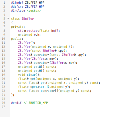
#ifndef ZBUFFER_HPP
#define ZBUFFER_HPP
#include <vector>

class ZBuffer
{
private:
	std::vector<float> buff;
	unsigned w,h;
public:
	ZBuffer();
	ZBuffer(unsigned w, unsigned h);
	ZBuffer(const ZBuffer& cpy);
	ZBuffer& operator=(const ZBuffer& cpy);
	ZBuffer(ZBuffer&& mov);
	ZBuffer& operator=(ZBuffer&& mov);
	unsigned getW() const;
	unsigned getH() const;
	void clear();
	float& get(unsigned x, unsigned y);
	const float& get(unsigned x, unsigned y) const;
	float* operator[](unsigned y);
	const float* operator[](unsigned y) const;
};

#endif // ZBUFFER_HPP
ZBuffer.cpp
#include "ZBuffer.hpp"
#include <limits>
#include <cstring>

ZBuffer::ZBuffer() : w(0), h(0)
{

}

ZBuffer::ZBuffer(unsigned w, unsigned h) : buff(w*h), w(w), h(h)
{

}

unsigned ZBuffer::getH() const
{
	return h;
}

unsigned ZBuffer::getW() const
{
	return w;
}

void ZBuffer::clear()
{
	//memset(buff.data(),0,buff.size()*sizeof(float));
	for(auto& it : buff) {
		it = std::numeric_limits<float>::infinity();
		//it = 1.0f;
	}
}

float &ZBuffer::get(unsigned x, unsigned y)
{
	return buff[(y*w)+x];
}

const float &ZBuffer::get(unsigned x, unsigned y) const
{
	return buff[(y*w)+x];
}

float *ZBuffer::operator[](unsigned y)
{
	return &buff[y*w];
}

const float *ZBuffer::operator[](unsigned y) const
{
	return &buff[y*w];
}

ZBuffer::ZBuffer(const ZBuffer &cpy) : buff(cpy.buff), w(cpy.w), h(cpy.h)
{

}

ZBuffer &ZBuffer::operator=(const ZBuffer &cpy)
{
	this->buff = cpy.buff;
	this->w = cpy.w;
	this->h = cpy.h;
	return *this;
}

ZBuffer::ZBuffer(ZBuffer &&mov) : buff(std::move(mov.buff)), w(mov.w), h(mov.h)
{
	mov.w = 0;
	mov.h = 0;
}

ZBuffer &ZBuffer::operator=(ZBuffer &&mov)
{
	this->buff = std::move(mov.buff);
	this->w = mov.w;
	this->h = mov.h;
	mov.w = 0;
	mov.h = 0;
	return *this;
}
Next, we modify our pipeline by adding a pointer to the Z-Buffer to our uniform:

struct ModelUniform {
	ZBuffer* zbuff;
	std::shared_ptr<Texture> tex;
	TextureFiltering filtering;
	glm::mat4 model;
	glm::mat4 projection;
};
And finally, we make use of said Z-Buffer:
#include "ModelPipeline.hpp"
#include <glm/gtc/matrix_transform.hpp>

ModelVertexOut ModelVertexShader(const ModelUniform &uniform, const ModelVertexIn &vertex, const glm::ivec4 &viewport)
{

	ModelVertexOut out{ glm::projectNO(vertex.POS,uniform.model,uniform.projection,viewport), vertex.TEXCOORD, vertex.COLOUR };
	return out;
}

void ModelFragmentShader(Texture &framebuffer, const glm::ivec2 &point, const ModelUniform &uniform, const ModelVertexOut &v0, const ModelVertexOut &v1, const ModelVertexOut &v2, float w0, float w1, float w2)
{
	if(!uniform.tex) return;
	if(point.x < 0 || point.y < 0) return;
	const float z = ((w0 * v0.POS.z) + (w1 * v1.POS.z) + (w2 * v2.POS.z));
	float& zbuffpoint = uniform.zbuff->get(point.x,point.y);
	if(z >= 0.0f && z <= zbuffpoint) {
	glm::vec2 texCoord = {
					(w0 * v0.TEXCOORD.r) + (w1 * v1.TEXCOORD.r) + (w2 * v2.TEXCOORD.r),
					(w0 * v0.TEXCOORD.g) + (w1 * v1.TEXCOORD.g) + (w2 * v2.TEXCOORD.g)
					};
	glm::vec4 colourKernel = uniform.tex->sample(texCoord,point,uniform.filtering) * glm::vec4{
					(w0 * v0.COLOUR.r) + (w1 * v1.COLOUR.r) + (w2 * v2.COLOUR.r),
					(w0 * v0.COLOUR.g) + (w1 * v1.COLOUR.g) + (w2 * v2.COLOUR.g),
					(w0 * v0.COLOUR.b) + (w1 * v1.COLOUR.b) + (w2 * v2.COLOUR.b),
					(w0 * v0.COLOUR.a) + (w1 * v1.COLOUR.a) + (w2 * v2.COLOUR.a)
					};
	zbuffpoint = z;
	framebuffer.setPixelDithered(point,point,colourKernel);
	}
}
And modify our rendering loop to make sure it gets cleared every time...
void SoftwareRendererSystem::render()
{
	renderBuffer.clearToColour(glm::vec4(0.0f, 0.5f, 1.0f, 0.0f));
	zbuff.clear();
	pipeline.renderTriangles(vertices.data(),indices.data(), indices.size() );
	SDL_UpdateTexture(framebuffer.get(), nullptr, renderBuffer.getRawPixels(), renderBuffer.getStride() );
	SDL_RenderCopy(renderer.get(), framebuffer.get(), nullptr, nullptr);
	SDL_RenderPresent(renderer.get());
	SDL_Delay(16);
}
And, we got something better!

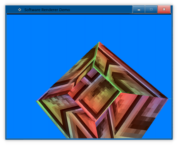
More observant viewers may have noticed something being wrong with our rendered shape. It seems warpy. Like the texture is warping.
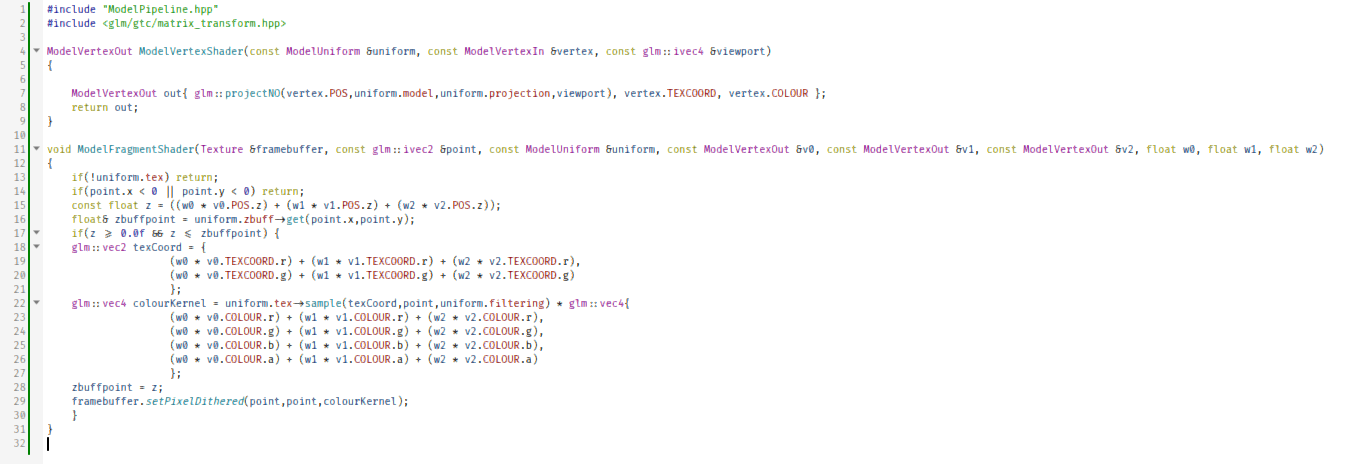
And that is because we are using affine texture mapping. To get perspective-correct texture-mapping, we'll need to divide up all our per-vertex attributes with the Z-coordinate after running the vertex shader, then multiply them with our Z-coordinate again in the fragment shader.
And if we do just that...
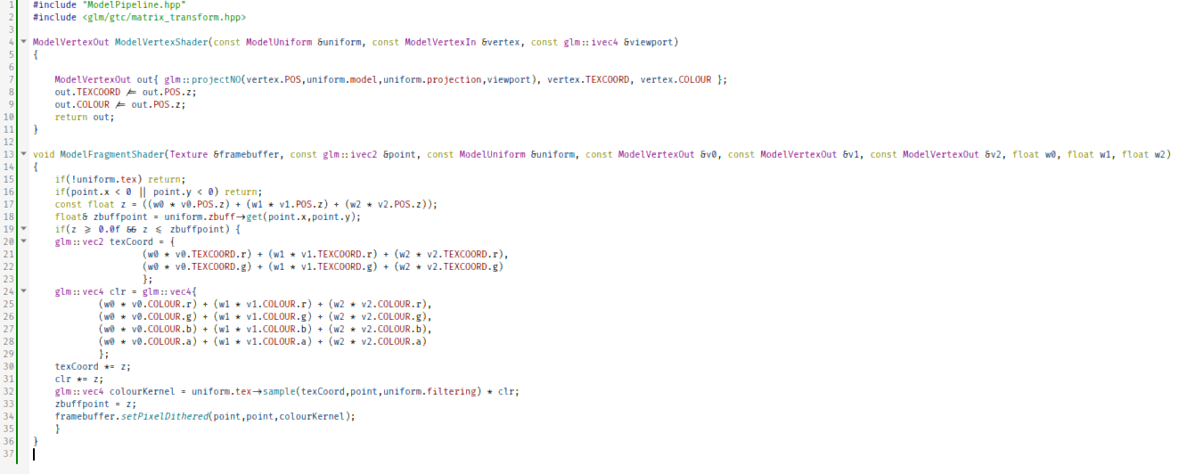
#include "ModelPipeline.hpp"
#include <glm/gtc/matrix_transform.hpp>

ModelVertexOut ModelVertexShader(const ModelUniform &uniform, const ModelVertexIn &vertex, const glm::ivec4 &viewport)
{

	ModelVertexOut out{ glm::projectNO(vertex.POS,uniform.model,uniform.projection,viewport), vertex.TEXCOORD, vertex.COLOUR };
	out.TEXCOORD /= out.POS.z;
	out.COLOUR /= out.POS.z;
	return out;
}

void ModelFragmentShader(Texture &framebuffer, const glm::ivec2 &point, const ModelUniform &uniform, const ModelVertexOut &v0, const ModelVertexOut &v1, const ModelVertexOut &v2, float w0, float w1, float w2)
{
	if(!uniform.tex) return;
	if(point.x < 0 || point.y < 0) return;
	const float z = ((w0 * v0.POS.z) + (w1 * v1.POS.z) + (w2 * v2.POS.z));
	float& zbuffpoint = uniform.zbuff->get(point.x,point.y);
	if(z >= 0.0f && z <= zbuffpoint) {
	glm::vec2 texCoord = {
					(w0 * v0.TEXCOORD.r) + (w1 * v1.TEXCOORD.r) + (w2 * v2.TEXCOORD.r),
					(w0 * v0.TEXCOORD.g) + (w1 * v1.TEXCOORD.g) + (w2 * v2.TEXCOORD.g)
					};
	glm::vec4 clr = glm::vec4{
			(w0 * v0.COLOUR.r) + (w1 * v1.COLOUR.r) + (w2 * v2.COLOUR.r),
			(w0 * v0.COLOUR.g) + (w1 * v1.COLOUR.g) + (w2 * v2.COLOUR.g),
			(w0 * v0.COLOUR.b) + (w1 * v1.COLOUR.b) + (w2 * v2.COLOUR.b),
			(w0 * v0.COLOUR.a) + (w1 * v1.COLOUR.a) + (w2 * v2.COLOUR.a)
			};
	texCoord *= z;
	clr *= z;
	glm::vec4 colourKernel = uniform.tex->sample(texCoord,point,uniform.filtering) * clr;
	zbuffpoint = z;
	framebuffer.setPixelDithered(point,point,colourKernel);
	}
}
We get perspective-correct texture mapping!
Except, we have a problem...
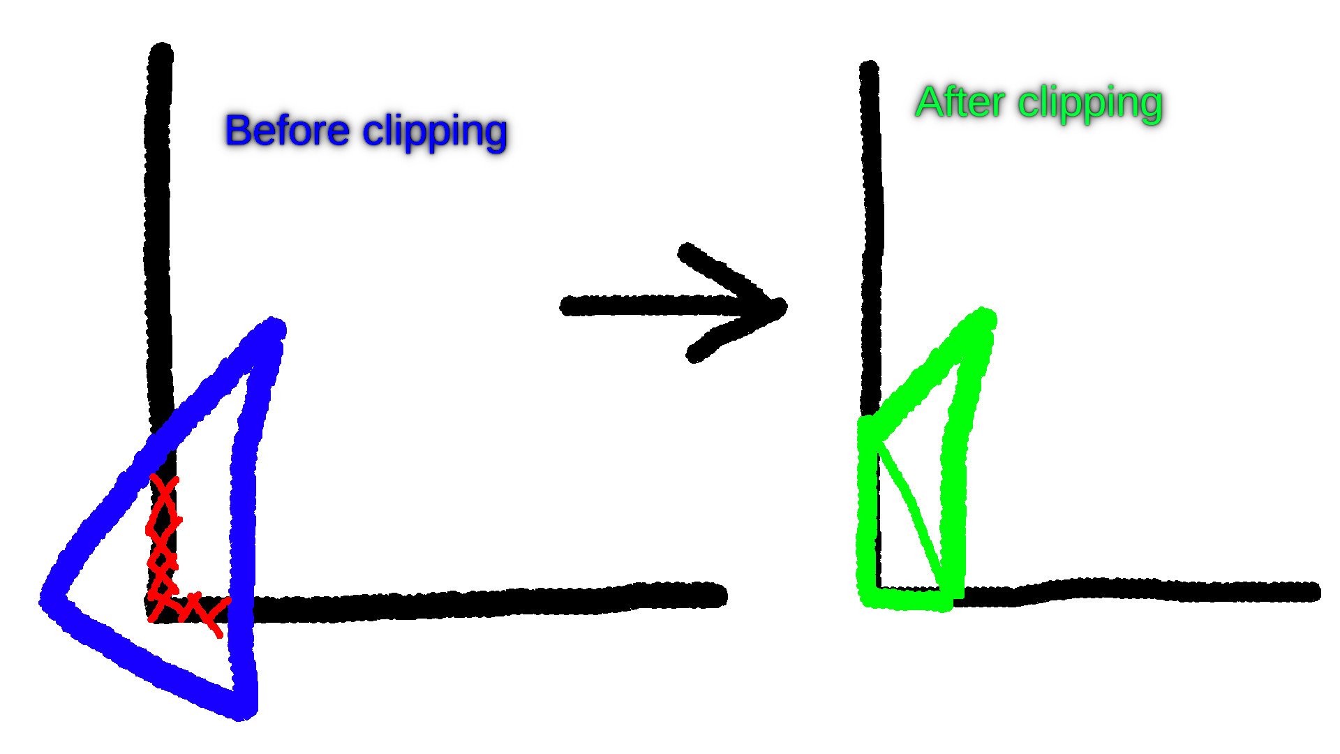
Clipping
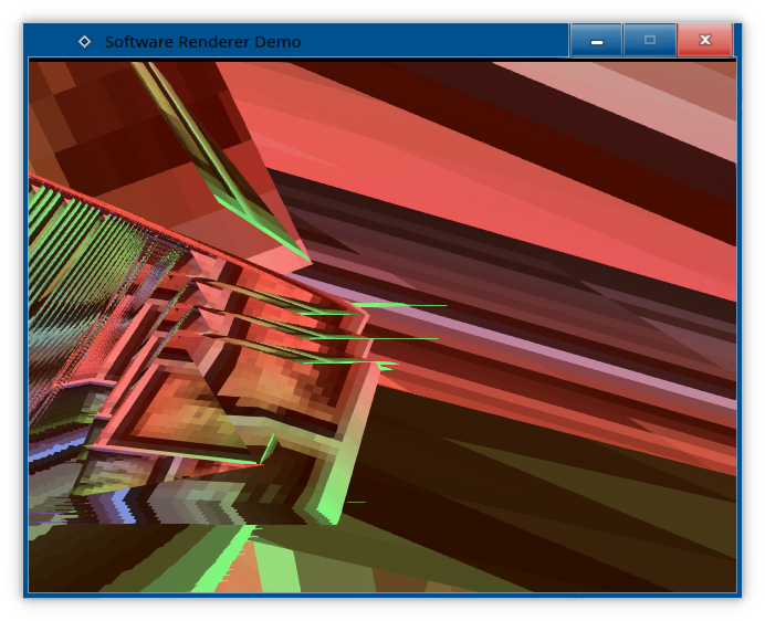
Notice what happens when you move too close to the model.

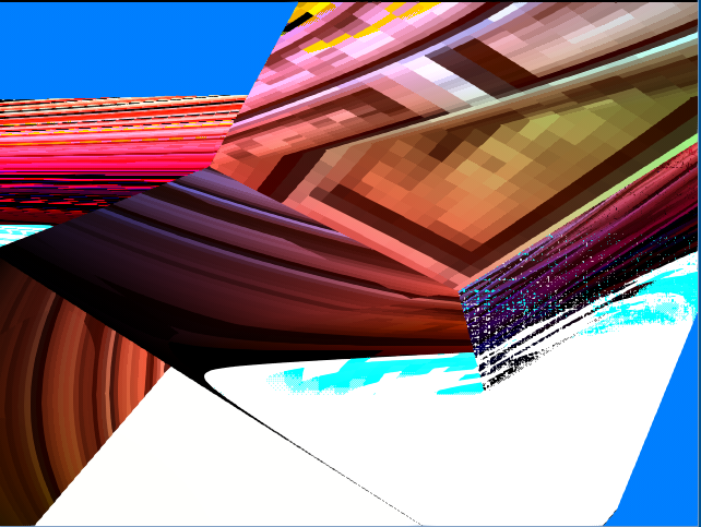
Our perspective-correction fails, and we also get some funky and trippy artifacts going on. What's the cause? The lack of clipping.
We need to clip our triangles. But what does that even mean? Well, it means we simply don't render anything that is outside the bounds of the screen.
But aren't we already refusing to render what falls outside the screen? Well, not truly. Sure, when we rasterize our triangles, in our loop, we define the amount of scanlines accordingly, but we could optimize this further by checking if the triangle even needs to be rendered at all.
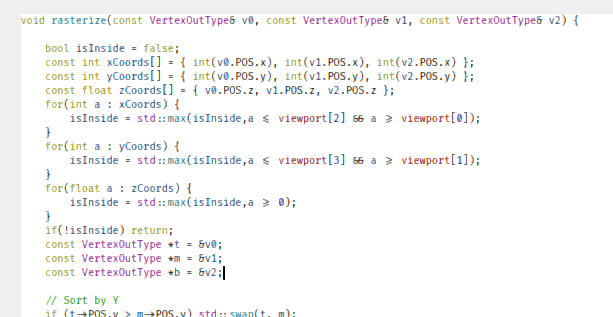
	void rasterize(const VertexOutType& v0, const VertexOutType& v1, const VertexOutType& v2) {

		bool isInside = false;
		const int xCoords[] = { int(v0.POS.x), int(v1.POS.x), int(v2.POS.x) };
		const int yCoords[] = { int(v0.POS.y), int(v1.POS.y), int(v2.POS.y) };
		const float zCoords[] = { v0.POS.z, v1.POS.z, v2.POS.z };
		for(int a : xCoords) {
			isInside = std::max(isInside,a <= viewport[2] && a >= viewport[0]);
		}
		for(int a : yCoords) {
			isInside = std::max(isInside,a <= viewport[3] && a >= viewport[1]);
		}
		for(float a : zCoords) {
			isInside = std::max(isInside,a >= 0);
		}
		if(!isInside) return;
		const VertexOutType *t = &v0;
		const VertexOutType *m = &v1;
		const VertexOutType *b = &v2;

		// Sort by Y
		...
Now we know up-front, if a triangle needs to be rendered or not - if all of its coordinates fall outside the viewport, or the triangle has a wrong Z-coordinate, we simply won't render the triangle at all. This saves us the sorting, the splitting, the looping over the scanlines, etc.
But it's not enough.
When a triangle is partially outside the bounds of the screen - or is too close to the viewer in regards to its Z-coordinate -, we need to clip it, which is to say, we have to split it.
But how do we go about doing just that?
There are four widely known algorithms for clipping triangles: the Greiner–Hormann clipping algorithm, the Sutherland–Hodgman algorithm, the Vatti clipping algorithm, and last but not least, the Weiler–Atherton clipping algorithm.
But before we implement any of them, we might want to do a little bit of refactoring....
Vertex Interpolation
So far, the interpolation of all of our vertex attributes took place in the fragment shader. This leads to repeated code that will be prone to errors. So I propose that we move this code into our vertex definitions.
To demonstrate on the BasicVertexOut:

struct BasicVertexOut {
	glm::vec3 POS;
	glm::vec4 COLOUR;
	inline static BasicVertexOut split(const BasicVertexOut& t, const BasicVertexOut& m, const BasicVertexOut& b, float dy, float iy) {
		return { glm::vec3(
						t.POS.x + ((b.POS.x - t.POS.x) / dy) * iy,
						m.POS.y,
						t.POS.z + ((b.POS.z - t.POS.z) / dy) * iy
						),
					glm::vec4(
						t.COLOUR.r + ((b.COLOUR.r - t.COLOUR.r) / dy) * iy,
						t.COLOUR.g + ((b.COLOUR.g - t.COLOUR.g) / dy) * iy,
						t.COLOUR.b + ((b.COLOUR.b - t.COLOUR.b) / dy) * iy,
						t.COLOUR.a + ((b.COLOUR.a - t.COLOUR.a) / dy) * iy
						) };
	}
	inline static BasicVertexOut interpolate(const BasicVertexOut& v0, const BasicVertexOut& v1, const BasicVertexOut& v2, float w0, float w1, float w2, bool perspectiveCorrect) {
		BasicVertexOut out = {
							glm::vec3(  // POS
							(v0.POS.x * w0) + (v1.POS.x * w1) + (v2.POS.x * w2), // X
							(v0.POS.y * w0) + (v1.POS.y * w1) + (v2.POS.y * w2), // Y
							(v0.POS.z * w0) + (v1.POS.z * w1) + (v2.POS.z * w2) // Z
							),
							glm::vec4( // COLOUR
							(v0.COLOUR.x * w0) + (v1.COLOUR.x * w1) + (v2.COLOUR.x * w2), // X
							(v0.COLOUR.y * w0) + (v1.COLOUR.y * w1) + (v2.COLOUR.y * w2), // Y
							(v0.COLOUR.z * w0) + (v1.COLOUR.z * w1) + (v2.COLOUR.z * w2), // Z
							(v0.COLOUR.w * w0) + (v1.COLOUR.w * w1) + (v2.COLOUR.w * w2) // W
							)
					};
		if(perspectiveCorrect) out.COLOUR *= out.POS.z; // We're assuming that the COLOUR attribute of each vertex was divided by POS.z prior to calling this function
		return out;
	}
};
This interpolate() function needs to be added to every vertex output struct now.
This will allow us to simplify the signature of our fragment shaders, after we modified the basic rendering pipeline.
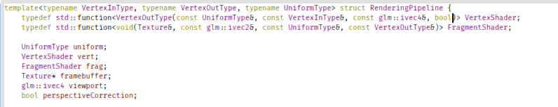
template<typename VertexInType, typename VertexOutType, typename UniformType> struct RenderingPipeline {
	typedef std::function<VertexOutType(const UniformType&, const VertexInType&, const glm::ivec4&, bool)> VertexShader;
	typedef std::function<void(Texture&, const glm::ivec2&, const UniformType&, const VertexOutType&)> FragmentShader;

	UniformType uniform;
	VertexShader vert;
	FragmentShader frag;
	Texture* framebuffer;
	glm::ivec4 viewport;
	bool perspectiveCorrection;
	...
	void renderScanline(float areaReciprocal, int y, int minX, int maxX, const VertexOutType& v0, const VertexOutType& v1, const VertexOutType& v2) {
		// Clamp the scanline's left and right ends into the viewport
		minX = std::max(minX,viewport[0]);
		maxX = std::min(maxX,viewport[2]);
		// Okay, let's render!
		for(int x = minX; x < maxX; ++x) {
			const glm::vec2 p = glm::vec2(float(x)+0.5f,float(y)+0.5f);
			const float w0 = edgeFunction(v1.POS, v2.POS, p) * areaReciprocal;
			const float w1 = edgeFunction(v2.POS, v0.POS, p) * areaReciprocal;
			const float w2 = edgeFunction(v0.POS, v1.POS, p) * areaReciprocal;
			frag(*framebuffer,glm::ivec2(x,y),uniform, VertexOutType::interpolate(v0,v1,v2,w0,w1,w2,perspectiveCorrection));
		}
	}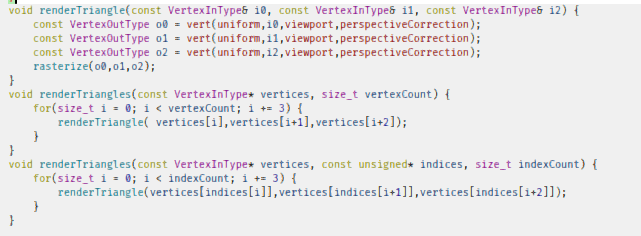
	void renderTriangle(const VertexInType& i0, const VertexInType& i1, const VertexInType& i2) {
		const VertexOutType o0 = vert(uniform,i0,viewport,perspectiveCorrection);
		const VertexOutType o1 = vert(uniform,i1,viewport,perspectiveCorrection);
		const VertexOutType o2 = vert(uniform,i2,viewport,perspectiveCorrection);
		rasterize(o0,o1,o2);
	}
	void renderTriangles(const VertexInType* vertices, size_t vertexCount) {
		for(size_t i = 0; i < vertexCount; i += 3) {
			renderTriangle( vertices[i],vertices[i+1],vertices[i+2]);
		}
	}
	void renderTriangles(const VertexInType* vertices, const unsigned* indices, size_t indexCount) {
		for(size_t i = 0; i < indexCount; i += 3) {
			renderTriangle(vertices[indices[i]],vertices[indices[i+1]],vertices[indices[i+2]]);
		}
	}
This means that we need to add that boolean parameter to our vertex shaders to account for perspective-correction, but otherwise, our codebase was slightly simplified.
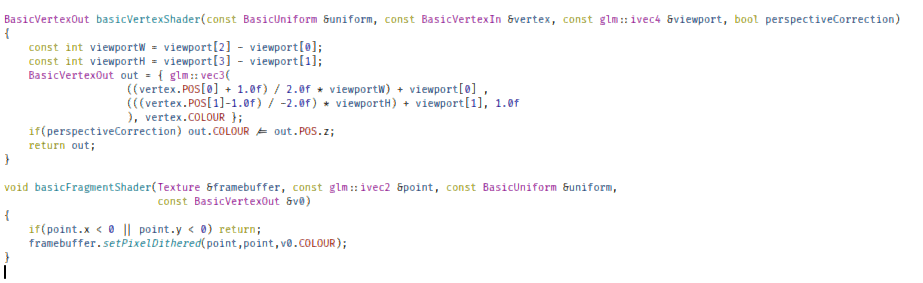
BasicVertexOut basicVertexShader(const BasicUniform &uniform, const BasicVertexIn &vertex, const glm::ivec4 &viewport, bool perspectiveCorrection)
{
	const int viewportW = viewport[2] - viewport[0];
	const int viewportH = viewport[3] - viewport[1];
	BasicVertexOut out = { glm::vec3(
					((vertex.POS[0] + 1.0f) / 2.0f * viewportW) + viewport[0] ,
					(((vertex.POS[1]-1.0f) / -2.0f) * viewportH) + viewport[1], 1.0f
					), vertex.COLOUR };
	if(perspectiveCorrection) out.COLOUR /= out.POS.z;
	return out;
}

void basicFragmentShader(Texture &framebuffer, const glm::ivec2 &point, const BasicUniform &uniform,
						 const BasicVertexOut &v0)
{
	if(point.x < 0 || point.y < 0) return;
	framebuffer.setPixelDithered(point,point,v0.COLOUR);
}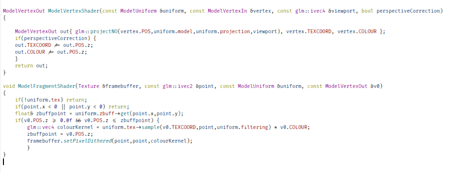
ModelVertexOut ModelVertexShader(const ModelUniform &uniform, const ModelVertexIn &vertex, const glm::ivec4 &viewport, bool perspectiveCorrection)
{

	ModelVertexOut out{ glm::projectNO(vertex.POS,uniform.model,uniform.projection,viewport), vertex.TEXCOORD, vertex.COLOUR };
	if(perspectiveCorrection) {
	out.TEXCOORD /= out.POS.z;
	out.COLOUR /= out.POS.z;
	}
	return out;
}

void ModelFragmentShader(Texture &framebuffer, const glm::ivec2 &point, const ModelUniform &uniform, const ModelVertexOut &v0)
{
	if(!uniform.tex) return;
	if(point.x < 0 || point.y < 0) return;
	float& zbuffpoint = uniform.zbuff->get(point.x,point.y);
	if(v0.POS.z >= 0.0f && v0.POS.z <= zbuffpoint) {
		glm::vec4 colourKernel = uniform.tex->sample(v0.TEXCOORD,point,uniform.filtering) * v0.COLOUR;
		zbuffpoint = v0.POS.z;
		framebuffer.setPixelDithered(point,point,colourKernel);
		}
}
Clippin' for real
Now that we have vastly simplified our shaders, and have provided for a way to interpolate vertices outside of the fragment shader, we need to implement clipping. I already mentioned there being four algorithms. So which one will we choose?
Two out of the four I mentioned - Vatti and Weiler-Atherton - are 2D-only, so that leaves us with Greiner–Hormann and Sutherland–Hodgman. I'm going with the latter, because it has pseudocode written on Wikipedia.
But before we go ahead and try to translate the pseudocode found on the Wikipedia page to C++ code, we need to keep a few things in mind:
Dynamic lists lead to malloc() calls for each added element, which is bad for real-time applications.
We need to replace it with a fixed-size stack. But how?
We are dealing with triangles and triangles only, so we only need to account for three inputs every single time.
We are limited to only 6 clip edges:
{ -1, 0, 0, 1 },{ 1, 0, 0, 1 },{ 0, -1, 0, 1 },{ 0, 1, 0, 1 },{ 0, 0,0 -1, 1 }and{ 0, 0,0 1, 1 }Within the process of clipping for a single edge, for every vertex, the algorithm is guaranteed to push either one or two vertices onto the stack.
But we need to run the aforementioned loop for every edge we wish to clip the triangle against, which is to say, 6 times.
Worst case scenario is
6*6=36vertices?
Because every iteration of the algorithm (we run as many iterations as we have clipping edges), uses the previous iteration of the algorithm was its input list, we need to maintain two fixed-size stacks.
So, with this in mind, we'll create a helper template.
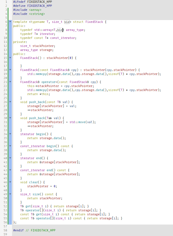
#ifndef FIXEDSTACK_HPP
#define FIXEDSTACK_HPP
#include <array>
#include <cstring>

template <typename T, size_t siz> struct FixedStack {
public:
	typedef std::array<T,siz> array_type;
	typedef T* iterator;
	typedef const T* const_iterator;
private:
	size_t stackPointer;
	array_type storage;
public:
	FixedStack() : stackPointer(0) {

	}
	FixedStack(const FixedStack& cpy) : stackPointer(cpy.stackPointer) {
		std::memcpy(storage.data(),cpy.storage.data(),sizeof(T) * cpy.stackPointer);
	}
	FixedStack& operator=(const FixedStack& cpy) {
		this->stackPointer = cpy.stackPointer;
		std::memcpy(storage.data(),cpy.storage.data(),sizeof(T) * cpy.stackPointer);
		return *this;
	}
	void push_back(const T& val) {
		storage[stackPointer] = val;
		++stackPointer;
	}
	void push_back(T&& val) {
		storage[stackPointer] = std::move(val);
		++stackPointer;
	}
	iterator begin() {
		return storage.data();
	}
	const_iterator begin() const {
		return storage.data();
	}
	iterator end() {
		return &storage[stackPointer];
	}
	const_iterator end() const {
		return &storage[stackPointer];
	}
	void clear() {
		stackPointer = 0;
	}
	size_t size() const {
		return stackPointer;
	}
	T& get(size_t i) { return storage[i]; }
	T& operator[](size_t i) { return storage[i]; }
	const T& get(size_t i) const { return storage[i]; }
	const T& operator[](size_t i) const { return storage[i]; }
};

#endif // FIXEDSTACK_HPP
Now we can go ahead and create yet another helper class: the VertexClipper.
Okay, so we need to clip three vertices to eight edges, right? What's so hard about that? Let's just implement the Sutherland–Hodgman algorithm and get over i!
Luckily, someone else already did the bulk of the dirty work for us, so what we have to do is take a good luck at his work, and modify it with the optimization I mentioned before (using a fixed-size stack instead of a dynamic list).
#ifndef VERTEXCLIPPER_HPP
#define VERTEXCLIPPER_HPP
#include "FixedStack.hpp"
#include <glm/glm.hpp>

template <typename T> int sgn(T val)
{
	return (T(0) < val) - (val < T(0));
}

template <typename VertexType> struct VertexClipper {
	typedef FixedStack<VertexType,36> VertexStack;
	typedef FixedStack<unsigned,36> IndexStack;
	IndexStack inputList, outputList;
	VertexStack vertices;
	glm::vec4 getClippingEdge(int i) {
		switch (i) {
		case 0: return glm::vec4(-1, 0, 0, 1);
		case 1: return glm::vec4( 1, 0, 0, 1);
		case 2: return glm::vec4( 0,-1, 0, 1);
		case 3: return glm::vec4( 0, 1, 0, 1);
		case 4: return glm::vec4( 0, 0,-1, 1);
		case 5: return glm::vec4( 0, 0, 1, 1);
		default:
			return glm::vec4(0.0f, 0.0f, 0.0f, 0.0f);
		}
	}

	void clipToEdge(const glm::vec4& clippingEdge) {
		if(inputList.size() < 3) return;
		outputList.clear();
		unsigned idxPrev =  inputList[0];
		outputList.push_back(idxPrev);
		const VertexType& vertPrev = vertices[idxPrev];
		float dpPrev = (clippingEdge.x * vertPrev.POS.x) + (clippingEdge.y * vertPrev.POS.y) + (clippingEdge.z * vertPrev.POS.z) + (clippingEdge.w * vertPrev.POS.w);
		for(size_t j = 1; j < inputList.size(); ++j) {
			unsigned idx = inputList[j];
			const VertexType& vert = vertices[idx];
			float dp = (clippingEdge.x * vert.POS.x) + (clippingEdge.y * vert.POS.y) + (clippingEdge.z * vert.POS.z) + (clippingEdge.w * vert.POS.w);
			if (dpPrev >= 0) outputList.push_back(idxPrev);

			if (sgn(dp) != sgn(dpPrev))
			{
				float t = dp < 0 ? dpPrev / (dpPrev - dp) : -dpPrev / (dp - dpPrev);
				VertexType vOut = VertexType::interpolate(vertices[idxPrev], vertices[idx],  1.0f-t, t, false);
				vertices.push_back(vOut);
				outputList.push_back((unsigned)(vertices.size() - 1));
			}
			idxPrev = idx;
			dpPrev = dp;
		}
		inputList = outputList;
	}

	void clipTriangle(const VertexType& v0, const VertexType& v1, const VertexType& v2) {
		vertices.clear();
		vertices.push_back(v0);
		vertices.push_back(v1);
		vertices.push_back(v2);
		inputList.clear();
		outputList.clear();
		inputList.push_back(0);
		inputList.push_back(1);
		inputList.push_back(2);
		for(int i = 0; i < 6; ++i) {
			clipToEdge(getClippingEdge(i));
		}
	}
};

#endif // VERTEXCLIPPER_HPP
There's quite a lot to unpack here, and I'll try my best:
We have our six clipping edges:
{ -1, 0, 0, 1 },{ 1, 0, 0, 1 },{ 0, -1, 0, 1 },{ 0, 1, 0, 1 },{ 0, 0,0 -1, 1 }and{ 0, 0,0 1, 1 }We first push our vertices to the stack, along with the indices.
For each of the six clipping edges, we run the following algorithm:
If we have less than 3 inputs, we don't do anything. Otherwise we clear the ouput stack.
We take the very first index from the output list, and use as the first "previous index" variable. It's gonna be important later on.
For every index on the input stack, we do this:
We calculate the dot products of the clipping edge with the vertices pointed to by the previous index and the current index.
If the previous index's vertex is inside the edge (has a positive or zero dot product), we push it onto the output stack.
If the sign of the two dot products are different, calculate the intersection between the previous vertex and the current vertex, interpolating to the point where it's on the clipping edge. We then push this new vertex onto the vertex stack, and its index onto the output stack.
The next iteration's previous index is the current index we operated on in this iteration.
We copy the previous iteration's outputs to our inputs.
Oh great, one more functions we'll have to add to our vertex output class. Ugh. We need an overload of the interpolate() function to interpolate between only two vertices, not three. Okay, that's trivial enough, we just copy-paste our existing interpolate functions, and simply remove parts of it.
Except there is one problem. A major problem.
Everything at its apropriate time
So far, our vertex shaders have produced screen-space coordinates for us, which has worked well for us so far. However, now it has come to majorly bite us in the behind, because this whole clipping thing is not going to work with purely signed numbers.
We'll need normalized numbers between 1 and -1. We'll need clip-space coordinates.
This means some modifications of our pipelines. Especially our vertex shaders.
This means that our vertex shaders will no longer take viewports as arguments, as they will output heterogenous coordinates.
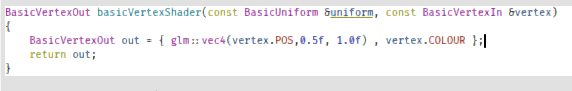
BasicVertexOut basicVertexShader(const BasicUniform &uniform, const BasicVertexIn &vertex)
{
	BasicVertexOut out = { glm::vec4(vertex.POS,0.5f, 1.0f) , vertex.COLOUR };
	return out;
}
This obviously means saying goodbye to our trusty old glm::project() function too.
ModelVertexOut ModelVertexShader(const ModelUniform &uniform, const ModelVertexIn &vertex)
{
	glm::vec4 tmp = glm::vec4(vertex.POS,1.0f);
	tmp = uniform.model * tmp;
	tmp = uniform.projection * tmp;
	ModelVertexOut out{ tmp, vertex.TEXCOORD, vertex.COLOUR };
	return out;
}
Basically, we do by hand what glm::project() did for us "automatically", minus the W-divison and the conversion to screenspace.
Obviously, now we'll have to do the conversion to screenspace in the pipeline template, but before that, we'll do the clipping.
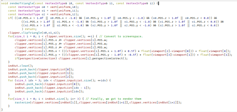
void renderTriangle(const VertexInType& i0, const VertexInType& i1, const VertexInType& i2) {
	const VertexOutType o0 = vert(uniform,i0);
	const VertexOutType o1 = vert(uniform,i1);
	const VertexOutType o2 = vert(uniform,i2);
	if( ((o0.POS.x > 1.0f || o0.POS.x < -1.0) && (o0.POS.y > 1.0f || o0.POS.y < -1.0) && (o0.POS.z > 1.0f || o0.POS.z < 0.0)) &&
			((o1.POS.x > 1.0f || o1.POS.x < -1.0) && (o1.POS.y > 1.0f || o1.POS.y < -1.0) && (o1.POS.z > 1.0f || o1.POS.z < 0.0)) &&
			((o2.POS.x > 1.0f || o2.POS.x < -1.0) && (o2.POS.y > 1.0f || o2.POS.y < -1.0) && (o2.POS.z > 1.0f || o2.POS.z < 0.0))
			) return;
	clipper.clipTriangle(o0,o1,o2);
	for(size_t i = 0; i < clipper.vertices.size(); ++i) { // Convert to screenspace.
		clipper.vertices[i].POS.x /= clipper.vertices[i].POS.w;
		clipper.vertices[i].POS.y /= clipper.vertices[i].POS.w;
		clipper.vertices[i].POS.z /= clipper.vertices[i].POS.w;
		clipper.vertices[i].POS.x = (((clipper.vertices[i].POS.x + 1.0f) * 0.5f) * float(viewport[2]-viewport[0])) + float(viewport[0]);
		clipper.vertices[i].POS.y = (((clipper.vertices[i].POS.y - 1.0f) * -0.5f) * float(viewport[3]-viewport[1])) + float(viewport[1]);
		if(perspectiveCorrection) clipper.vertices[i].perspectiveCorrect();
	}
	indOut.clear();
	indOut.push_back(clipper.inputList[0]);
	indOut.push_back(clipper.inputList[1]);
	indOut.push_back(clipper.inputList[2]);
	for (size_t idx = 3; idx < clipper.inputList.size(); ++idx) {
		indOut.push_back(clipper.inputList[0]);
		indOut.push_back(clipper.inputList[idx - 1]);
		indOut.push_back(clipper.inputList[idx]);
	}
	for(size_t i = 0; i < indOut.size(); i+= 3) { // Finally, we got to render them
		rasterize(clipper.vertices[indOut[i]],clipper.vertices[indOut[i+1]],clipper.vertices[indOut[i+2]]);
	}
}
And, we've got clipping!
It's not perfect, and we still get some artifacts, but it's much better than before, and at least we no longer get funky effects when we get too close.
However, before we truly wrap up, there is one more subject we need to cover.
Alpha-Blending
So far, all shapes that we rendered we opaque. But what if we wanted to render transparent objects with transparent textures, like this?

Well, if we just try to render it, we get this:
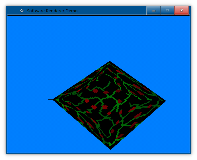
Doesn't look quite right, now does it?
We'll need to do alpha-blending.

#ifndef TEXTURE_HPP
#define TEXTURE_HPP
#include <glm/glm.hpp>
enum TextureFiltering {
NEAREST_NEIGHBOUR,
DITHERED,
BILINEAR
};
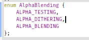
enum AlphaBlending {
ALPHA_TESTING,
ALPHA_DITHERING,
ALPHA_BLENDING
};
class Texture
{
public:
virtual ~Texture() = default;
// Data getters
virtual int getWidth() const = 0;
virtual float getWidthF() const = 0;
virtual int getHeight() const = 0;
virtual float getHeightF() const = 0;
virtual int getStride() const = 0;
// Pixel manipulation
virtual void getPixel(const glm::ivec2& pos, glm::vec4& colourKernel) const = 0;
inline glm::vec4 getPixel(const glm::ivec2& pos) const {
glm::vec4 tmp;
getPixel(pos,tmp);
return tmp;
}
virtual void setPixel(const glm::ivec2& pos, const glm::vec4& colourKernel) = 0;
virtual void setPixelDithered(const glm::ivec2& pos, const glm::ivec2& screenpos, const glm::vec4& colourKernel) = 0;
bool setPixelWithBlending(const glm::ivec2& pos, const glm::ivec2& screenpos, const glm::vec4& colourKernel, AlphaBlending blendingType);
virtual void* getRawPixels() = 0;
virtual const void* getRawPixels() const = 0;
virtual void sample(const glm::vec2& pos, const glm::ivec2& screenpos, TextureFiltering filteringType, glm::vec4& colourKernel) const;
inline glm::vec4 sample(const glm::vec2& pos, const glm::ivec2& screenpos, TextureFiltering filteringType) const {
glm::vec4 tmp;
sample(pos,screenpos,filteringType,tmp);
return tmp;
}
virtual void clearToColour(const glm::vec4& colourKernel) = 0;
};
#endif // TEXTURE_HPP
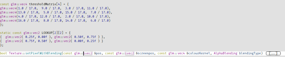
const glm::vec4 thresholdMatrix[4] = {
glm::vec4(1.0 / 17.0, 9.0 / 17.0, 3.0 / 17.0, 11.0 / 17.0),
glm::vec4(13.0 / 17.0, 5.0 / 17.0, 15.0 / 17.0, 7.0 / 17.0),
glm::vec4(4.0 / 17.0, 12.0 / 17.0, 2.0 / 17.0, 10.0 / 17.0),
glm::vec4(16.0 / 17.0, 8.0 / 17.0, 14.0 / 17.0, 6.0 / 17.0)
};
static const glm::vec2 LOOKUP[2][2] = {
{ glm::vec2( 0.25f, 0.00f ), glm::vec2( 0.50f, 0.75f ) },
{ glm::vec2( 0.75f, 0.50f ), glm::vec2( 0.00f, 0.25f ) }
};
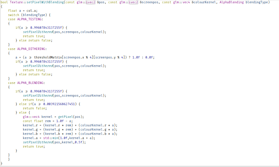
bool Texture::setPixelWithBlending(const glm::ivec2 &pos, const glm::ivec2 &screenpos, const glm::vec4 &colourKernel, AlphaBlending blendingType)
{
float a = colourKernel.a;
switch (blendingType) {
case ALPHA_TESTING:
{
if(a >= 0.99607843137255f) {
setPixelDithered(pos,screenpos,colourKernel);
return true;
} else return false;
}
case ALPHA_DITHERING:
{
a = (a >= thresholdMatrix[screenpos.x % 4][screenpos.y % 4]) ? 1.0f : 0.0f;
if(a >= 0.99607843137255f) {
setPixelDithered(pos,screenpos,colourKernel);
return true;
} else return false;
}
case ALPHA_BLENDING:
{
if(a >= 0.99607843137255f) {
setPixelDithered(pos,screenpos,colourKernel);
return true;
} else if(a >= 0.003921568627451) {
return false;
} else {
glm::vec4 kernel = getPixel(pos);
const float rem = 1.0f - a;
kernel.r = (kernel.r * rem) + (colourKernel.r * a);
kernel.g = (kernel.g * rem) + (colourKernel.g * a);
kernel.b = (kernel.b * rem) + (colourKernel.b * a);
kernel.a = std::min(1.0f,kernel.a + a);
setPixelDithered(pos,screenpos,kernel);
return true;
}
}
}
}So, what's there to unpack?
We defined three alpha-blending modes: Alpha-testing, alpha-dithering and alpha-blending.
Alpha-testing simply tests if the new pixel is above a certain threshold, and overwrites the old pixel if it is.
If the alpha is above that threshold, we can overwrite the Z-buffer variable too. This means we don't need to order our triangles.
Alpha-blending actually blends the two colours, if the alpha value is anything other than 1 or 0 - that is, anywhere between 1 and 0.
But how do we know if we need to overwrite the Z-buffer variable, or don't? Generally, the rule of thumb is to write to the Z-buffer if the alpha is above 0, but then we have to render opaque objects before transparent objects, and render transparent objects sorted by Z. Yikes.
Alpha-dithering fakes alpha-blending by dithering the alpha and reducing it to 1-bit.
It also ensures that we have either completely overwritten a pixel, or kept the old one, ensuring that we don't need to sort any objects, and we can render in any speed we want.
We implemented said modes.
But this also requires a slight modification of our fragment shader, as well as our uniform.
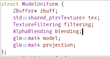
struct ModelUniform {
	ZBuffer* zbuff;
	std::shared_ptr<Texture> tex;
	TextureFiltering filtering;
	AlphaBlending blending;
	glm::mat4 model;
	glm::mat4 projection;
};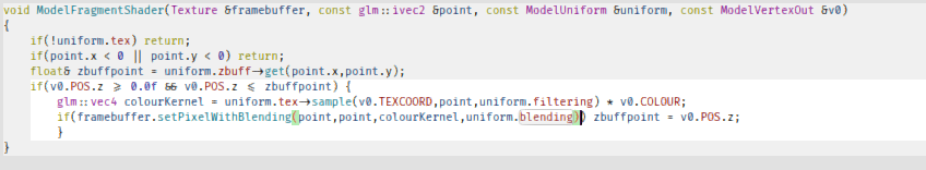
void ModelFragmentShader(Texture &framebuffer, const glm::ivec2 &point, const ModelUniform &uniform, const ModelVertexOut &v0)
{
	if(!uniform.tex) return;
	if(point.x < 0 || point.y < 0) return;
	float& zbuffpoint = uniform.zbuff->get(point.x,point.y);
	if(v0.POS.z >= 0.0f && v0.POS.z <= zbuffpoint) {
		glm::vec4 colourKernel = uniform.tex->sample(v0.TEXCOORD,point,uniform.filtering) * v0.COLOUR;
		if(framebuffer.setPixelWithBlending(point,point,colourKernel,uniform.blending)) zbuffpoint = v0.POS.z;
	}
}
Aaaand, after setting the renderer to use alpha-dithering, we got alpha-dithering!
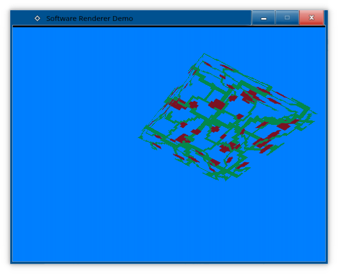
And that about wraps up the series about software rendering.
As usual, the code in the tutorial is uploaded to Github. If it is requested, I may write a tutorial about Vulkan or OpenGL, or even a second software rendering series. Until then, please donate.
Outro
Congratulations! Hopefully, now you learned how to write a software renderer, or at the very least, how the GPU works under the hood! Obviously, there are many ways this software renderer could be improved:
Using fixed-point numbers instead of floating-point numbers can speed up performance, as Geri said.
De-generalization: This software renderer uses "shaders", which requires it to be generic. But if it was turned into a completely fixed-function pipeline specialized for a pre-set task like an existing game (engine) instead of desperately trying to emulate the GPU, it could be optimized nicely.
Implementing aggressive triangle-culling: because clipping is not enough.
More optimized code overall.