Note
This is an english translation of my practical work report on the Fiber Optic Installation Project in the Central Government of Badung Regency, Bali from June-August 2012 where I highlight the computer network configuration using Cisco devices and the theme I raised in this report is the simulation of Cisco equipment using Cisco Packet Tracer.
This practical work report is an obligation for my bachelor's in the Department of Electrical Engineering, Faculty of Engineering, Udayana University. However, this report has never been published anywhere and the copyright is fully mine and it has been 8 years since this report was written where conditions on the field have changed so it is less likely to reveal secrets that can be dangerous for the Badung Regency Government. Therefore, I declare that this report is open, may be copied, may be republished, and may be sold on condition to give attribution by mentioning my name as the original author and state that this report is open at this link (customized CC-BY-SA).
Abstract
The Fiber Optic Installation Project in the Central Area of the Badung Regency Government is a path to switch the conventional government system to ICT-based (Information Communication Technology). Project implementation is carried out by conducting an environmental survey, preparing tools, materials, and labor, making fiber optic lines, planting optical fibers, connecting optical fibers to devices in each building, configuring the network and clean the area to be exactly as before. This report will discuss the network configuration part.
What needs to be understood in order to do this configuration is understanding device usage, understanding IP addresses, understanding VLAN (Virtual Local Area Network), understanding static routes and RIP (Routing Information Protocol), remote login, and NAT (Network Address Translation).
Configuration was carried out in Building 10, namely the Central Government of Badung Regency Transportation and Information Agency from September 4, 2012 to September 8, 2012. The tools needed to perform the configuration are a laptop, UTP cable, DB9M-USB converter cable, and Cisco console cable. The software needed for configuration is a serial terminal and a telnet client. The first configuration planning is the provision of VLAN (Virtual Local Area Network) allocations to each agency in each building. Second, the allocation of IP addresses on each VLAN. The third is the allocation of IP addresses for each device. The fourth is topology formation.
The first configuration is on the local network. The IP address for each switch is on VLAN 1. Each switch is assigned a VLAN ID based on the services contained in the building. The connection from the switch to the multilayer switch is given trunk mode so that all VLAN IDs can pass. In a multilayer switch port connected to the Internet network is given an IP address and a multilayer switch is given a routing configuration. Routing is also set up on other routers. Router 2900 is configured with NAT (Network Address Translation) to translate the local IP address from the inside into a Public IP address outward. All devices are debug enabled, logged, and Telnet login enabled.
In the IP address configuration there is a waste of IP addresses. It is recommended to reconfigure the subnet mask. It is recommended again to label more ports and VLAN IDs to make management easier.
Chapter 1 Introduction
1.1 Background
ICT (Information Communication Technology) is a term that covers information, communication, telecommunications, and computers. With the existence of ICT, it replaces the place of information that is real objects. Libraries can be replaced with web pages on the Internet network, documents in the form of paper and books can be replaced with servers containing electronic documents, correspondence by post mails can be replaced with email (electronic mail). Information on the Internet is also available in the form of pictures and videos. The advantage of this method compared to the classical method is the efficiency of energy, place and time. With ICT, all forms of information contained can be accessed anytime and anywhere quickly (without having to waste energy and time to go somewhere and are limited by time to access information).
Many Government Centers have switched to ICT-based, meaning that they have begun to utilize ICT technology for the benefit of the Government. One example of sending documents via post or sending documents by directly visiting the delivery destination is starting to be replaced with email. The place where the author carried out practical work, namely in the Badung District Government Center has switched to ICT-based.
Practical Work at the Central Government of Badung Regency is to carry out the Fiber Optic Installation Project in all Services in the Central Government of Badung Regency. The Project Owner is Dishubkominfo (Department of Transportation, Communication and Informatics) Badung Regency Government, the executor is PT. Skill Surabaya, and the supervisor is CV. Bali Info Data. The author is on the supervisory side.
Of all the stages of Fiber Optic Network Infrastructure Development in the Central Area of the Badung Regency Government, this Job Training Report is specifically at the ICT configuration stage. To make it easier to absorb, this computer network configuration will be simulated in the Cisco Packet Tracer network simulator program. The simulation was carried out because the author was on the supervisor's side where the configuration stages could not be shown directly, because the ICT configuration in the Badung Regency Government was fixed, not allowed for reconfiguration. This program is used because the tools used are almost all Cisco products.
1.2 Objective
Report the computer network configuration on the Fiber Optic Network Infrastructure Development Project in the Central Area of the Badung Regency Government, and simulate it in Cisco Packet Tracer.
1.3 Benefit
Have a computer network configuration documentation on this project.
Understand more about the configuration of this computer network by linking existing theories.
By simulating it in Cisco Packet Tracer, it can be faster and easier to understand.
1.4 Practical Work Execution
This Practical Work is the Infrastructure Development for Fiber Optic Networks carried out from June-September 2012 in the Central Area of the Badung Regency Government. In general, this project stages are
Area survey, purchasing tools and materials, and finding labor.
Digging holes at several points and drilling for passing Fiber Optic cables under the ground, as well as installing Fiber Optic lines in each basement of the building.
Optical Fiber Connections from the Communication and Information Technology Transportation Agency to each service, there are 12 buildings, and perform performance testing of Fiber Optic cables.
Installation of Switches and Routers at the Communication and Information Technology Agency and Switches in each building as a fiber optic link from the Communication and Information Technology Department of Transportation to each building.
Configure Switches and Routers, and perform performance testing.
Cleaning and tidying up.
1.5 Scope and Boundaries
Configuration discussion is starting from Cisco Switch c3750e from all buildings to modems at the Department of Communications, Communications and Information.
Discusses IP (Internet Protocol) Addresses, Virtual Local Area Networks, Static Routes, Router Information Protocols, Network Address Translation, Telnet Login, the types of cables used.
Not discussing network security and bandwidth limitation, both on Cisco ASA and Mikrotik because network security and bandwidth limitation are still in the planning stage, will be implemented in the future.
Using Cisco Packet Tracer as a simulator with the limitations of using UTP cable instead of Fiber Optic Switch 2960-24TT cable as a replacement for the c3750e Switch, Multilayer Switch 3560-24 PS as a replacement for the Multilayer Switch cat4500e, and Router 2811 as a replacement for Mikrotik, Modem, ASA Router, and Router 2900 is due to the absence of this module in Cisco Packet Tracer.
1.6 Writing System
Chapter 1 Introduction contains the background, objectives, benefits, implementation of practical work and the scope and limitations.
Chapter 2 Literature Review contains IP addresses, Switches and Routers, Virtual Local Area Networks, Static Routes, Router Information Protocols, Network Address Translation, Telnet Login, UTP Cables, and Cisco console cables.
Chapter 3 The Badung Regency Government ICT Network Configuration contains the time and place, tools and materials, network configuration plans, and configuration of each device.
Chapter 4 Discussion of network configuration leading from Multilayer Switch cat4500e to Modem, local network configuration, and connection test.
Chapter 5 Closing contains conclusions and suggestions.
Chapter 2 Literature Review
2.1 Introduction
To perform this configuration requires knowledge of when using a straight-through or crossover type RJ45 ethernet cable to connect between devices. In this ICT configuration, a switch is used as a link between many devices and a router as a link to the Internet. Addressing devices is used IPV4 (Internet Protocol Version 4). In-depth knowledge of IPV4 is required for a central level ICT configuration of Government. Knowledge of VLAN (Virtual Local Area Network) is required to facilitate local network management, and a little NAT (Network Address Translation) for connecting to the Internet. Telnet login is optional, for easy management. Then the theories that need to be known are described in this chapter.
2.2 RJ45 Ethernet Cable and DB9 - RJ45 Cable
The RJ45 Ethernet cable that connects the computer to the switch, switch to the router using a straight-through cable. Meanwhile, to connect between computers, between switches, between routers, and computers with a router using a crossover cable. The RJ45 ethernet cable consists of 8 pins, of which 4 are used as minus voltage transmitters, plus voltage transmitters, minus receivers, and plus receivers. There are straight-thru and crossover types because there are differences in the location of the transmitter and receiver (The Internet Center, 2013).

Figure 2.1 RJ45 Ethernet cable arrangement (The Internet Center, 2013)
The Cisco console cable is used to configure Cisco devices. This cable is a female DB9 to RJ45 male.


Figure 2.2 Arrangement of DB9 female to RJ45 male cable (WTI, 2013)
2.3 Switch and Router
A switch is a device that can connect between computers, between local networks, and between computers and local networks. In OSI (Open Systems Interconnection) the reference model works at layer 2, namely datalink. Switches have multiple ports and work by forwarding incoming frames from a port to a destination port. The switch stores the hardware address and port location of the connected devices on a port.
Router is a device that connects between networks (currently between switches). In OSI (Open Systems Interconnection) the reference model works at layer 3, namely the network. Router works based on network address. The router determines the path to go to other networks (Gebali, 2008).
2.4 IP (Internet Protocol) Address
IP address or translated as IP address defines a host or a router to the Internet network, is a binary series of numbers. Computer networks and Internet networks today use IP addresses to indicate the identity of a device. This address is used as the identity of the data sender and receiver. Therefore IP addresses must be unique and universal. Currently there are 2 versions of IP, namely IP version 4 and IP version 6.IPV4 consists of 32 bits and is written in binary or decimal form, while IPV6 consists of 128 bits and is written in binary or hexadecimal form, currently used is IPV4, IPV6 for the future.
IPV4 is written with a subnet mask or prefix. Writing in decimal divided by byte or 8 bits (xxxxxxxx.xxxxxxx.xxxxxxx.xxxxxxx).
Example 2.1
An IP address 192.168.0.1 (11000000.10101000.00000000.00000001) 255.255.255.0 (11111111.1111111.1111111.00000000). Writing in the prefix is 192.168.0.1/24 (x.x.x.x/n), the number 24 represents the number of bits 1 in the subnet mask. Therefore, the author of the subnet mask can only be divided into 2 poles, namely the left side of the number 1, and the right part of the number 0 (it cannot be random).
The subnet mask shows the number of hosts in a network, shows the network ID (identity), and the host ID. To find the network ID for an IP address, perform the AND operation on the given subnet mask.
Example 2.2
From example 2.1 192.168.0.1 (11000000.10101000.00000000.00000001) 255.255.255.0 (11111111.1111111.1111111.00000000), 11000000.10101000.00000000.00000001 AND 11111111.1111111.1111111.00000000 result are 11000000.10101000.00000000.00000000 where 192.168.0.0 is network ID, and host is 192.168.0.1.
IP addresses can be class or classless. If it is a class, it is divided into 5 classes, namely A, B, C, D, and E. What is used in general is A - C, while D is for multicast and E experimentally, and is used for future needs (Sutanta, 2005). Here are 2 tables showing the class and a table regarding the prefix.
Table 2.1 IP address class (Sutanta, 2005)


Table 2.2 Prefix (Sutanta, 2005)


If the subnet mask is deepened, the subnet mask can determine the number of IP addresses on a network. The number of IP addresses can be calculated from bit 1 on the right combined with all bits 0 in the subnet mask.
Example 2.3
255.255.255.0 (11111111.1111111.1111111.00000000), then the number of IP addresses = 10000000(2) is 256(10), 255.255.255.224 (11111111.1111111.11111111.11100000), then the number of IP addresses = 100000(2) is 32(10).
Of all IP addresses in a network, the first IP address is used as a network ID, the last IP address is used as a broadcast ID, and if it is a WAN (Wide Area Network) network, one more IP address is needed as a gateway (to another network), usually an address after the network ID.
Example 2.4
192.168.0.1 (11000000.10101000.00000000.00000001) 255.255.255.0 (11111111.1111111.1111111.00000000), then if 11000000.10101000.00000000.00000001 AND 11111111.1111111.1111111.00000000 result is 11000000.10101000.00000000.00000000 is 192.168.0.0 is a network ID, with the host identity 192.168.0.1, with the subnet mask 255.255.255.0 (11111111.1111111.1111111.00000000), then the total number of IP addresses is 10000000 (2) = 256 (10), the first address 192.168.0.0 as the network ID and the last address is 192.168.0.255 as the broadcast ID, and can be selected from 192.168.0.1 - 192.168.0.254 as the gateway, and the rest can be used for the host (Inixindo, 2005). For further exploration, please see the following table.
Table 2.3 Example of IP address management


In conclusion, the fewer the number of bits 1 in the subnet mask, the greater the number of hosts and the less the number of network IDs, and vice versa.
2.5 VLAN (Virtual Local Area Network)
A VLAN is a group of devices on 1 or more LANs that are configured to communicate as if they are connected to the same cable, where in fact they are on different LAN segments. VLANs are based on logic rather than physics, because they are flexible.
VLAN defines a broadcast domain at layer 2. Broadcast domain is a set of devices that will receive broadcast frames from any device. Layer 2 Switches create broadcast domains based on switch configurations. Switches are multiport bridges that can create multiple broadcast domains. One VLAN can be a broadcast domain. VLANs cannot communicate with each other because they are in different broadcast domains. To connect between VLANs it is necessary to use a router or layer 3 switch (Cisco, 2004).


Figure 2.3 Example VLAN (Cisco, 2004)
2.6 Static Route and RIP (Routing Information Protocol)
Static Route is a permanent routing mechanism. The path to a network on a router device is determined directly by the administrator. In the static route setting of a router, it is the next hop when it goes to a network.
RIP is a dynamic route, which is a routing mechanism that varies with time and is flexible. RIP adopts a distance-vector protocol where each router will provide information to neighboring routers about the path connected to the router. From this the router will estimate the distance of all the paths to reach other networks. After that the router will determine its own path based on the shortest distance according to router estimates from the results of exchanging information between neighboring routers (Stallings, 1998).
2.7 NAT (Network Address Translation)
IPV4 is running low, meaning that most of it is already in use around the world. Therefore IPV6 was developed. While waiting for IPV6 to be implemented there is a solution to save IP addresses in version 4, namely NAT. IPV4 addresses are classified into 2 types, namely private IP and global IP. Global IP is an IP address that is only owned by 1 device worldwide and is known in the Internet network. Meanwhile, private IP is an unknown IP address on the Internet network and is free to use by any device so that the owner can be more than 1. The private IP is 10.x.x.x 255.0.0.0, 172.16.x.x 255.255.0.0, and 192.168.x.x 255.255.255.0. Whereas 127.x.x.x 255.0.0.0 is used as the loopback. In addition, it is a global IP address (Inixindo, 2005).
NAT works by translating private IP to global IP and vice versa. For example a host array has private IP 192.168.10.2 - 192.168.10.254 255.255.255.0 and exits via router, gateway 192.168.10.1 255.255.255.0 which can NAT with global IP 202.130.0.5 255.255.255.0, for example to Google DNS 8.8.8.8 255.0.0.0. Then packets out of 192.168.10.2 - 192.168.10.254 will be translated to 202.130.0.5 before sending to 8.8.8.8. After that 8.8.8.8 will reply with the destination IP address 202.130.0.5, after which the router converts to the destination IP address to 192.168.10.x, depending on the sender (Peterson, 2003).
2.8 Telnet
Telnet is an application that works at OSI layer 7, which is an application that can perform remote login, which is entering a device using another computer. Telnet is very useful for remote work, which should come to the location of the device to enter the system, with telnet entry to the system can be done remotely. Telnet transmits data without encryption and is opened on port number 23 (Burgess, 2004).
Chapter 3 Configuration of the Badung Regency Government ICT Network
3.1 Introduction
The ICT network configuration in this report is the ICT configuration in the Badung Regency Government. ICT network configuration includes IP address addressing, VLAN identity allocation, debugging, routing, remote login, and NAT. The port usage on the device is also determined. The physical form of the configured tools can be seen in section 3.3 Tools and Materials in Figure 3.1 and Figure 3.2. IP addressing, port used, and VLAN can be seen in section 3.4 Configuration Plan.
3.2 Place and time
The configuration was carried out in Building 10, namely the Central Government of Badung Regency Transportation and Information Agency from 4 September 2012 to 8 September 2012.
3.3 Tools and Materials
Table 3.1 Tool


Table 3.2 Materials
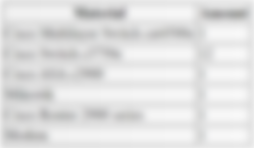


Figure 3.1 Multilayer Switch cat4500e, ASA, Mikrotik, Router 2900 from bottom to top


Figure 3.2 Switch C3750e in each building
3.4 Configuration Plan


Gambar 3.3 Network topology map
Table 3.3 Local network configuration
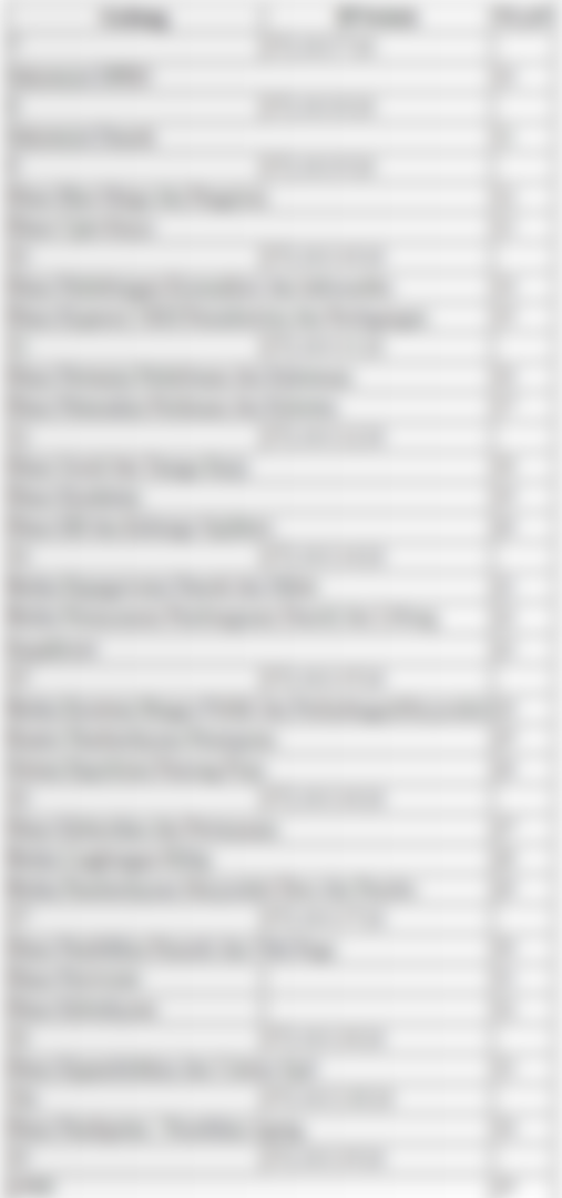

Table 3.4 VLAN configuration


Tabel 3.5 Konfigurasi Internet


Chapter 4 Discussion
4.1 Introduction
In the discussion, a simulation of ICT modeling and configuration was carried out at the Office of Communications and Information Technology, Badung Regency Government with the Cisco Packet Tracer program. A simulation was conducted because the ICT configuration in the Badung Regency Government was fixed and not allowed to be reconfigured or further configured. Therefore, the configuration stage is simulated in the Cisco Packet Tracer program, this program is used because the tool used is Cisco. The ICT configuration in the simulation is exactly the same as the ICT configuration in the field. There are only differences in the model of the tool as described in Chapter 1 section 1.5 Scope and Boundaries, and differences in interfaces.
In Section 4.2 Modem Setup is a public IP modeling where only certain IP addresses can be connected. In Section 4.3 Network Configuration Towards the Internet is the ICT configuration stage from Cisco Multilayer Switches to Modems. In section 4.4 NAT configuration is a configuration for converting local IP addresses to public IP addresses. In Section 4.5, Local Network Configuration is the configuration of Cisco Multilayer Switches to Cisco Switches in each Building. Section 4.6 Connection Test is a connection test using the ping application.
4.2 Modem Setup
The discussion of network configuration will be explained at the same time in the Cisco Packet Tracer simulation. First make a network topology. Starting from the modem configured IP address on the modem (although the modem is not a Cisco device, but its configuration is made close to its original function). According to table 3.5, the IP address at the entrance to the modem is 202.46.10.129/24. Routing used by all routers is RIP (Routing Information Protocol) version 2. The spanning-tree has been configured automatically, namely PVST.


Figure 4.1 Network Topology


Figure 4.2 Configuring the Modem
To enter the router you need the "enable" command.
Begin configuring the IP address on the interface by entering "configure terminal".
Command "hostname Modem" to give a name.
The command “access-list 1 permit 202.46.10.130” plus “access-list 1 deny any” so that it resembles the state of the field is configured so that only IP addresses 202.46.10.130/24 can enter.
To configure an interface, first enter the interface with the command "interface fastEthernet 0/0" (interface fastEthernet 0/0 is the interface connected to the Internet router in this simulation).
Give an IP address with the command "ip address 202.46.10.129 255.255.255.0", the command "ip access-group 1" to enforce access-list 1.
To start the interface with the command "no shutdown".
Finally, the command "end" to exit the configuration and command "write" to save the configuration.
4.3 Network Configuration Towards the Internet
Next, configure the Internet router. According to table 3.5, the Internet interface to the modem with the IP address is 202.46.10.130/24 (in the fastethernet interface simulation 0/1), while the interface from the Internet to Mikrotik has an IP address of 192.168.253.2/24 (in the fastethernet interface simulation 0/0). The configuration method is the same as giving an IP address to the modem, but does not do an "access-list".
Figure 4.3 Configuring an Internet Router
In addition to this configuration, the "no service password-encryption" command removes password encryption. The commands "service timestamps debug datetime msec" and "service timestamps log datetime msec" to record every time a configuration change occurs.
The "enable cisco password" and "enable cisco secret" commands give the "cisco" and "cisco" secret "passwords where required for telnet login. The command "line vty 0 4" followed by "cisco password" and "login" to activate the telnet server with the password "cisco".
"Exit" to exit a configuration. For routing, RIP version 2 is used where version 2 supports classless routing (not limited to classes A, B, or C) while version 1 can only route class, for example the 192.168.10.0 network reads immediately 192.168.10.0/24 even though what you want is 192.168.10.0/ 26 or other. "Redistribute static" means passing a static route when a static route is configured. "No auto-summary" to not activate auto-summary, which functions as class routing, which reads the IP address, whether it belongs to class A, B, or C, auto-summary can only be turned off in RIP version 2, and cannot be in version 1. Command "network 192.168.253.0" to add neighboring network information. According to Stallings regarding RIP in Chapter 2, each router will exchange information with neighboring routers in order to choose a path. The order is an order to introduce the neighbor. RIPv2 is not done on the 202.46.10.0/24 network because it is assumed to be a modem.
Therefore, a static route is added to the Internet with the command "ip route 0.0.0.0 0.0.0.0 202.46.10.129".
Each interface adds an "ip virtual-reassembly" to prevent attacks that take up the time and memory needed to compile packets of data.
Overall, this router configuration is similar to the Cisco Router 2900 configuration. The configuration method is the configuration in Figure 4.2 plus the configuration of Figure 4.3 based on table data 3.5.
This report does not discuss the proxy configuration, therefore in this simulation how to configure a router called Mikrotik is the same as a router configuration called Internet. According to table 3.5 the interface to the Internet (fastEthernet 0/1) is assigned the IP address 192.168.253.1/24. In a connection, for example, between the Internet and Mikrotik interfaces must be on the same network ID. 192.168.253.1/24 (from Mikrotik) and 192.168.253.2/24 (from the Internet), according to Sutanta in theory, the IP address in Chapter 2 is on the same network ID, namely 192.168.253.0/24. The interface to ASA has the IP address 192.168.101.2/24. RIPv2 is "network 192.168.253.0" and "network 192.168.101.0".
Cisco ASA is a device for firewalls. This report does not discuss data security, therefore in this simulation the Cisco ASA configuration method is the same as the Internet Router configuration. According to table 3.5 the interface to Mikrotik has an IP address of 192.168.101.1/24, according to Sutanta 192.168.101.2/24 and 192.168.101.1/24 are on the same network, namely 192.168.101.0/24. The interface to the NOC (Cisco multilayer switch cat4500e in the field) has an IP address of 172.16.128.2/24. RIPv2 is "network 192.168.101.0" and "network 172.16.0.0". "Network 172.16.0.0" is used because according to table 3.4 NOC will have IP networks of 172.16.0.0/24, 172.16.16.10.0/24 - 172.16.35.0/24, and 172.16.128.0/24. Therefore RIPv2 "Network 172.16.0.0" will deal with IP addresses 172.16.0.0 - 172.16.255.255.
How to configure Internet routers in Multilayer Switch NOC (Cisco Multilayer Switch cat4500e in the field). There is a slight difference. By default, all NOC interfaces on the NOC function as switches.
To give the IP address of the interface to ASA (gigabitethernet 0/1), that is, the switch mode is turned off with the command "no switchport". Then proceed with giving the IP address according to table 3.5 with the command "ip address 172.16.128.1 255.255.255.0" and the command "no shutdown" to turn on.
RIPv2 is "network 172.16.0.0", only 172.16.0.0 - 172.16.255.255 are connected according to table 3.4.
Assuming it can go to the Internet network as in the field, a static route is given with the command "ip route 0.0.0.0 0.0.0.0 172.16.128.2", meaning that it goes to all IP addresses of 0.0.0.0 with all subnet masks 0.0.0.0 through 172.16.128.2, namely the IP address interface in ASA is connected to the NOC.
In this simulation, the command "ip routing" is required to enable routing.


Figure 4.4 Configuring NOC
4.4 Configure NAT (Network Address Translation) on the Cisco Router 2900


Figure 4.5 Testing connection using PING from NOC
Based on all the above configurations it is not enough to connect from NOC to Modem. NOC to ASA, Mikrotik, and the Internet can be connected but not to the Modem. In fact, only the IP address 202.46.10.130 can be entered in the field.


Figure 4.6 Internet router can be connected to a modem
According to table 3.5 there are 2 public IPs, namely on the Internet and Modem. In order to connect to the modem, the incoming IP address must be converted to 202.46.10.130.


Figure 4.7 Configuring NAT on an Internet Router
First you have to create an access list that allows everyone to enter with the command "access-list 2 permit any", the name of the access here is access-list 2.
The command "ip nat inside source list 2 interface fastEthernet 0/1 overload" is a command to perform NAT (Network Address Translation). Ip nat inside converts the incoming IP address from the Internet router, based on access-list 2 (source list 2) is converted to exit via the fastethernet 0/1 interface, that is converted to the IP address assigned to the interface (202.46.10.130), overload command so that all types of incoming IP addresses are converted to 1 IP address.
After that, it needs to be installed from the data packet entry interface (fastEthernet 0/0) "ip nat inside", and on the data packet exit interface (fastEthernet 0/1) "ip nat outside". The configuration to go to the Internet network (exit the modem) has been completed.


Figure 4.8 Testing connection with PING from NOC to Modem
4.5 Local Network Configuration
The last configuration is on the LAN (Local Area Network), which is the configuration connecting all Cisco c3700e switches in all buildings to the Multilayer Switch cat4500e in building 10 (NOC). Providing VLAN identity per building and per service based on table 3.3. In this configuration, the interface of each VLAN in the NOC is made with an IP address based on table 3.4 and the table provides information on VLAN installation on several interfaces on the switch of each building. For how to configure the switches for each building is the same. So at this writing the local NOC configuration will be displayed and only 2 switch configurations from 2 buildings.


Figure 4.9 Local Network Topology


Figure 4.10 Local configuration on NOC 1
Depending on the device, the “VLAN database” command can be configured before the configure terminal or at the configure terminal, this command will enter VLAN settings. After that, enter the command "vlan 10" to add VLAN 10. Adding VLANs is done according to table 3.3 and table 3.4, adding VLAN 10 - VLAN 35.


Figure 4.11 Local configuration on NOC 2


Figure 4.12 Local configuration on NOC 3
Assigning an IP address to the VLAN 1 interface is a way to assign an IP address to a device. According to table 3.3 the IP address on the NOC is 172.16.0.10/24. The command "interface range fastEthernet 0/1 - 12" is a way to enter fastethernet 0/1 - fastethernet 0/12 at once. It was planned on this interface (connected to the switch of each building) so that all VLAN IDs can pass. So the command is "switchport mode trunk", there is a switch that must be given the command "switchport trunk encapsulation dot1Q", which is an IEEE (Intitute Electrical Electronic Engineer) 802.1Q standard, for VLAN standards. According to table 3.4 VLAN interfaces 10-35 are assigned an IP address.


Figure 4.13 Local configuration of Building 7 switches
The initial line is a general configuration performed on all devices, namely, service timestamps, service password-encryption, line vty 0 4 (telnet login), secret installation (MD5 password), installation on the VLAN interface 1. Gigabitethernet 1/1 interface is the interface that connected to the NOC. So that all VLANs can enter, then with the command "switchport mode trunk". Based on table 3.4, the fastethernet 0 / 1-4 interface is given the entry of only VLAN 10 with the commands "interface range fastethernet 0/1 - 4", "switchport mode access", and "switchport access vlan 10". In this simulation, so that VLAN 1 in each building is connected, each switch is given a default-gateway with the command "ip default-gateway 172.16.0.10", which is the default route to VLAN 1 NOC.


Figure 4.14 Providing default-gateway on Building 7 switches
Next is configuration on the Switch Building 12. The method is the same as Building 7, according to tables 3.3 and 3.4 VLAN 18-20 is installed. For other switch configurations, the method is the same. Then the configuration is complete, to see the configuration results you can type the command "show running-config".


Figure 4.15 Local configuration on Building 12 switch 1


Figure 4.16 Local configuration of Building 12 switch 2
4.6 Testing Connection
At this writing only a few tests were written. First, the computer is installed on the Building 7 switch on the fastethernet0/1 interface. After that configured and ping the interface VLAN 10 and Modem. After that, telnet to the NOC and switch Building 12.


Figure 4.17 IP PC0 Configuration


Figure 4.18 PING from PC0 to VLAN 10 and Modem


Figure 4.19 Telnet from PC0 to NOC and Building 12 switches


Figure 4.20 Laptop IP Configuration0


Figure 4.21 PING from Laptop0 to NOC and Modem


Figure 4.22 Telnet from Laptop0 to Building 7 switch and NOC
Chapter 5 Closing
5.1 Conclusion
The topology on this network is a tree. The local network consists of 12 switches and 1 multilayer switch. All buildings are connected to building 10. Each office is on 1 VLAN ID. The total VLAN used is 25 of VLAN 10 - Vlan 35, with a network ID of 172.16.10.0/24-172.16.35.0/24. Installation of a VLAN ID is carried out in 1 multilayer switch in 10 buildings and 12 switches in all buildings. The port that is connected from 12 switches to a multilayer switch is a trunk mode where all VLAN IDs can enter. Each switch and multilayer switch is assigned an IP address on VLAN 1 as if it were assigned an IP address on the device.
From the multilayer switch to the Internet network must pass through ASA, Mikrotik, Router, and Modem. The multilayer switch port to the Internet network functions as a router so that the switchport mode is turned off and assigned an IP address. After that the routing mode is activated, static routing is used for the Internet network, while for the internal use RIPv2 dynamic routing. Likewise in ASA, Mikrotik, and Router. The router is given 1 public IP. Everything that goes to the router goes to the modem, then to the Internet network, the private IP address is converted into a public IP with NAT.
For the purpose of processing all devices enabled log and debug for notification of changes in the device. Secret and password are activated for telnet purposes. Telnet server is activated so that you can remote login.
5.2 Suggestions
The suggestion that can be given is to improve the quality of the network configuration.
The first suggestion is to install a point-to-point IP address such as from a multilayer switch to ASA. Network ID 172.16.128.0/24 where there is waste of IP addresses. The IP address used with the subnet mask (255.255.255.0) is 254 IP addresses while 2 IP addresses are required. So it is better if 172.16.128.0/30 is the subnet mask 255.255.255.252. It is recommended for other settings to save IP addresses with a subnet mask.
The second suggestion is to label each port for a clear description of the port's function.
The final suggestion is on VLANs. It is easier if the multilayer switch is used as a VTP server, while the other is a VTP client so that the VLAN configuration is sufficient on the multilayer switch. It is better if each VLAN ID is named so that there is information on the device about which VLAN is using.
Bibliography
Burgess, M. 2004. Principles of Network and System Administration. John Wiley & Sons, Ltd. : Chicester
Cisco. 2004. Catalyst 4500 Series Switch Cisco IOS Software Configuration Guide. Cisco Systems, Inc : San Jose.
Gebali, F. 2008. Analysis of Computer and Communication Networks. Springer Science + Business Media : New York
Inixindo, S. 2005. Workshop Basic Internetworking. Graha Pena : Surabaya
Peterson, L. Davie, B. 2003. Computer Networks Third Edition. Morgan Kaufmann : San Fancisco
Stallings, W. 1998. High-Speed Networks TCP/IP and ATM Design Principles. Prentice-Hall, Inc. : New Jersey.
Sutanta, E. 2005. Komunikasi Data & Jaringan Komputer. Graha Ilmu : Yogyakarta.
The Internet Center. 2013. http://www.incentre.net/ethernet-wiring-diag.html. Diakses 24 Juli 2013.
Western Telematic Inc. 2013. http://www.wti.com/p-236-72-3383-01-cisco-rollover-console-cable-blue-db9-to-rj45-6.aspx. Diakses 24 Juli 2013.
Mirror

...and you will also help the author collect more tips.

Awesome