Electronics - Logic Gates
Those squares and rectangles that you never understand:
Since the 1960s, Technology has changed in an exponential way, with devices that are less than a quarter of the size of what they used to be 60 years before and that are at least 1000 times more powerful. All these advances came with the invention of the integrated circuit, a little chip made of semiconductor materials that can contain electronic circuits and has metallic conductors in order to establish electrical connections between the IC and the circuit It is connected to. However, the behavior of these devices and Its functions can be explainable in the form of diagrams, specifically logical diagrams that give us a hint of the journey of an electrical input to Its final output through the use of logic gates. In this article we'll explain what they exactly are, the types of gates and how they work. Let's begin by defining what a logic gate exactly is.
What is a Logic Gate?
These are devices that have particular logical properties that incorporate boolean operations within them, such as addition, substraction, division, inclusion or exclusion. They have a determined number of inputs (According to the type of gate and their specific functions) and an individual output for the result of the signal. The factors that differentiate them from one another are their shape (In a logical diagram) and their functioning.

When mentioning the signal and how It changes as It gets from the input to the output of a gate, we'll talk about the terms HIGH and LOW, meaning the first that the signal represents a logical 1 (Voltage Over the minimum required for an input/output to be in the HIGH state) and LOW a logical 0 (Voltage under the minimum required for an input/output to be in the HIGH state).
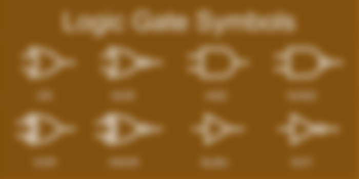
Types of Gates:
First, let's begin with the most commonly used, the AND and OR gates.
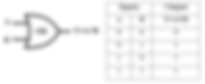
AND Gate
These gates are characterized by having a minimum of two inputs and one output, where the main condition is that both input signals have to be in the HIGH State (Logical 1) for the output to have a HIGH state. If one of the input signals has a LOW state, then the output will be in a LOW state, as It is highlighted in the next truth table.

If you look at It in an arithmetic way, you can see the output as a result of the product of the inputs.
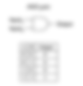
OR Gate
Like the AND gate, OR gates have a minimum of two inputs and one output, and Its functioning bases itself in an operation of addition between the inputs, where If one of these has a HIGH state, then the output of the gate will have a High State, or in a mathematical way:
Input(A) + Input(B) = Output

NOT Gate
Basically, the simplest one to understand, as It just inverts Its one and only input, giving the opposite state in the output. For example, if the input has a HIGH state, then the output will have a LOW state.
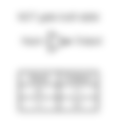

NAND Gate
The opposite of an AND Gate. If all the inputs (minimum of two) have a HIGH state, then the output will have a LOW State, turning the opposite If at least one has a LOW state. This is described in the truth table:


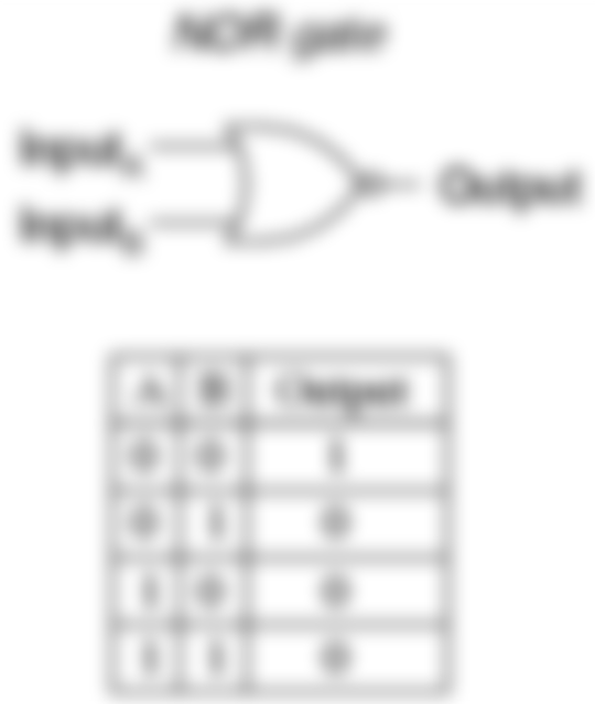
NOR Gate
The opposite of the NOR Gate. If at least one of the inputs has a high state, then the output level will be in a LOW state and if all the inputs have a LOW state, then the output will have a HIGH state.
XOR Gate:
A particular type of gate, as what It differentiates It from the OR Gate is that Its output will be in a HIGH state exclusively if one of the input is in a HIGH state. If both the inputs are in a LOW or HIGH State, then the output will be in a LOW state.

XNOR Gate:
As you might intuit, It is the opposite of the XOR Gate. If both inputs are in a HIGH or LOW State, then the output will return a HIGH state and If only one of the inputs is in a HIGH state, then the output will have a LOW state.


We hope that in the presented series of paragraphs, we could be able to explain logic gates in a simple and digestable way, so you can get a grasp of how logic diagrams work and get a deeper understanding of the behavior of a particular integrated circuit. In a next article we'll talk about the universality of NAND and NOR gates and how you can get the functioning of all the remaining gates with circuits based in just these two. Good Luck!